Apparatus and method for thermal conductivity detection in gas chomatography equipment

a technology of thermal conductivity and equipment, applied in the field of thermal conductivity detectors, can solve the problems of unfavorable stability and interference, tcd's are not as sensitive as other types of detectors, and the design of tcd's restricts the use of tcd's, so as to achieve good stability, fast response time, and maximum sensitivity

Inactive Publication Date: 2005-08-16
AGILENT TECH INC
View PDF11 Cites 26 Cited by
  • Summary
  • Abstract
  • Description
  • Claims
  • Application Information

AI Technical Summary

Benefits of technology

[0010]One feature of the present invention is to provide a thermal conductivity detec...

Problems solved by technology

TCD's are, however, often not as sensitive as other types of detectors.
This limitation of existing TCD designs restricts the use of TCD's in some instances.
Direct-type designs provide favorable sensitivity, but at the expense of unfavorable stability and interference.
By contrast, diffused-type designs are unfavorably diminished in sensitivity a...

Method used


Image

  • Apparatus and method for thermal conductivity detection in gas chomatography equipment
  • Apparatus and method for thermal conductivity detection in gas chomatography equipment
  • Apparatus and method for thermal conductivity detection in gas chomatography equipment

Examples


Embodiment Construction

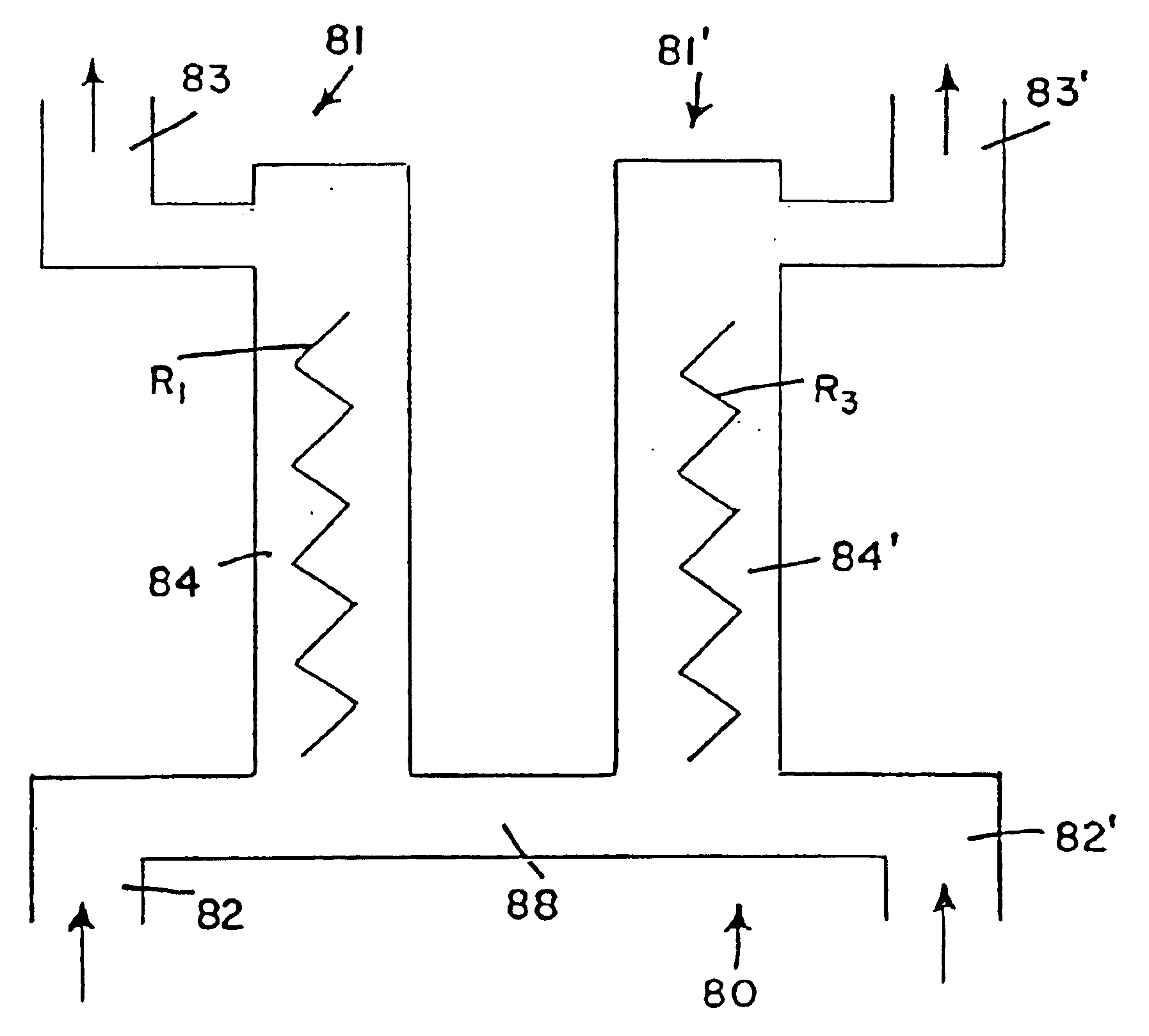
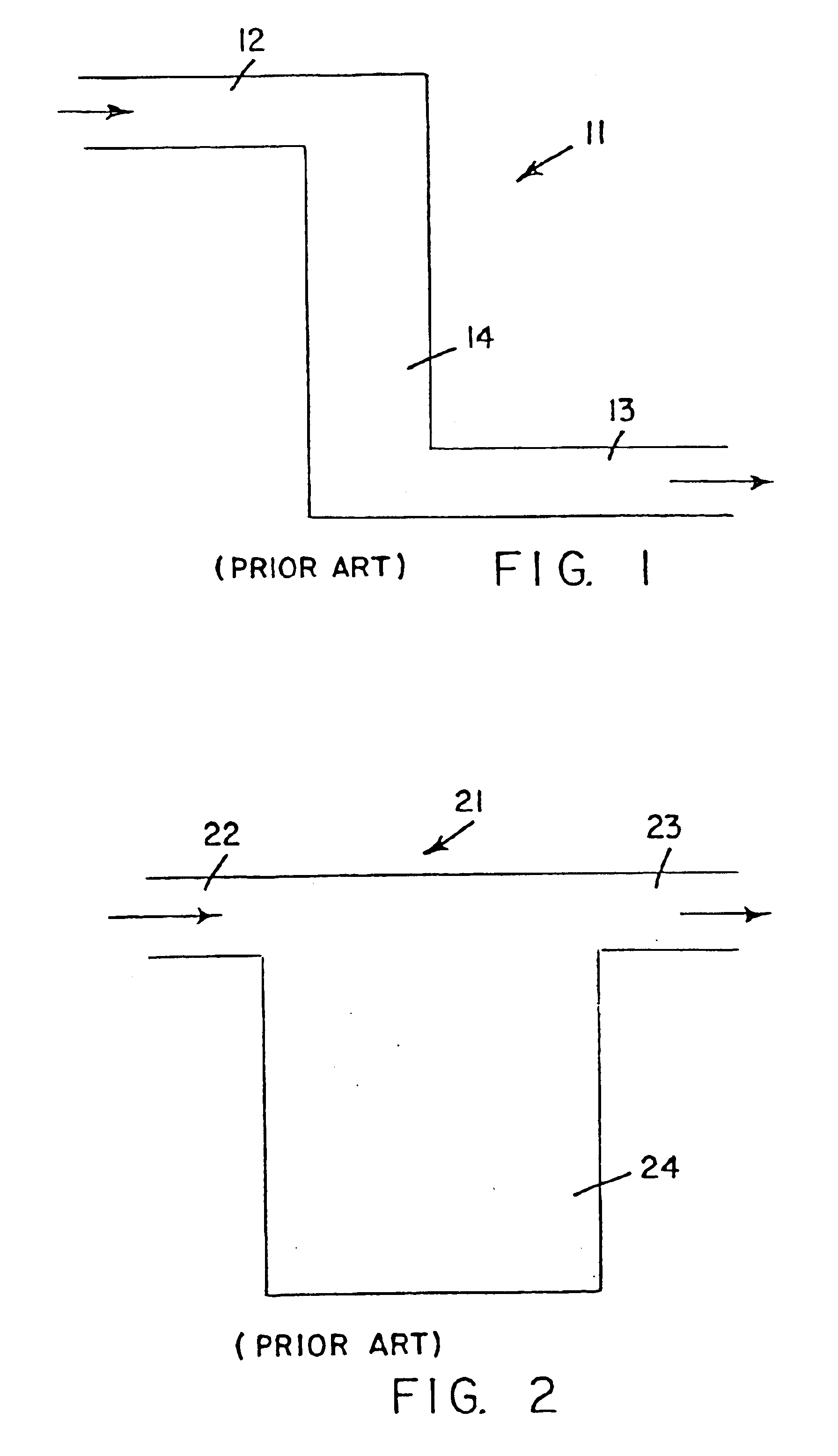
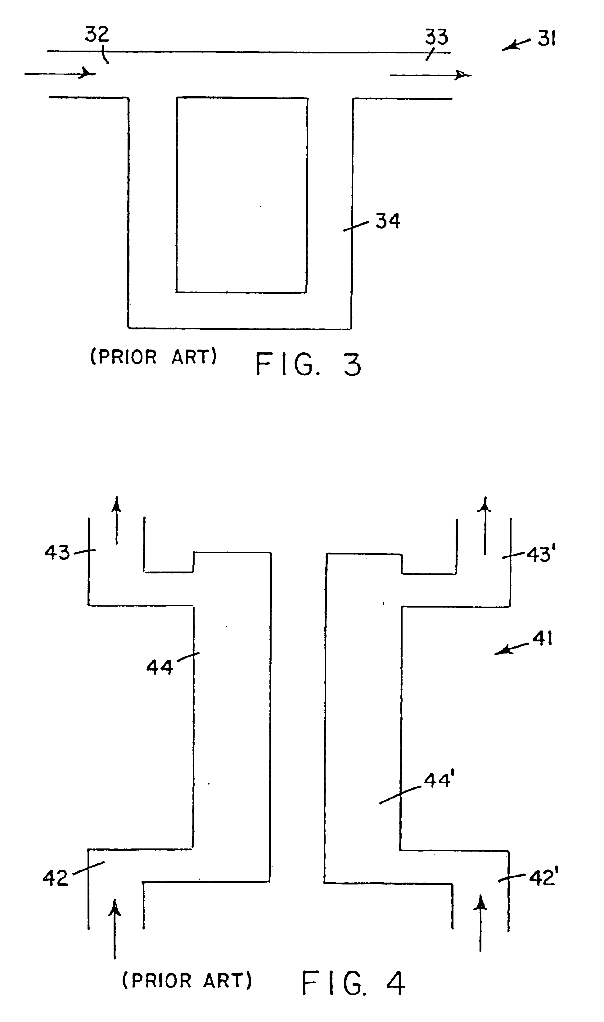
[0024]FIGS. 1 to 3 represent existing TCD designs that can be used with gas chromatographic equipment. Each design is used in a pair, as represented in FIGS. 4 and 5.

[0025]Referring to FIG. 1, a prior art direct-type TCD design 11 has an input end 12 and an output end 13. A detecting portion 14 is located between the input end 12 and output end 13. FIG. 2 shows a prior art diffused-type TCD design 21. FIG. 3 shows a prior art semi-diffused-type TCD design 31, which is essentially a hybrid of the direct-type and diffused-type designs of FIGS. 1 and 2.

[0026]In the case of FIG. 1, gas flows directly past the detecting portion 14. In FIG. 2, by contrast, the main detecting portion 24 is adjacent the direct path from the input end 22 to the output end 23. Accordingly, the detecting portion 24 detects gas, which diffuses from this main path.

[0027]In FIG. 3, gas that diffuses from the main path between an input end 32 and an output end 33 flows directly past the directing portion 34.

[0028]...


PUM


Abstract

A thermal conductivity detector includes separate sample gas and reference gas chambers. Each chamber has a gas inlet and a gas outlet and a sensor. The chambers are connected by at least one passageway. For example, a passageway can extend from the sample gas chamber to the reference gas chamber adjacent the gas inlets. As a further example, a passageway can be provided adjacent the gas outlets. More specifically, an exhaust passageway extends from the first passageway to the additional passageway and there is an exhaust outlet connected to the additional passageway.

Description

FIELD OF THE INVENTION[0001]The present invention relates to thermal conductivity detectors used in gas chromatography applications.BACKGROUND OF THE INVENTION[0002]Gas chromatography involves vaporizing an analytic sample and injecting the vaporized sample onto a head of a chromatographic column. The vaporized sample is transported through the chromatographic column by a flow of an inert gas. A detector is then used to determine different components of the sample.[0003]Various types of detectors can be used with gas chromatography equipment, and each type has particular advantages and disadvantages. One type of detector is a thermal conductivity detector, which for convenience is referred to hereinafter as a TCD. A TCD operates based on relative changes in the thermal conductivity of gas flowing through separate sample and reference cells of the TCD.[0004]TCD's are valued for their relative simplicity, their relatively large linear dynamic range, and their general response to both ...

Claims


Application Information

Patent Timeline
IPC IPC(8): G01N27/14G01N30/66G01N30/00G01N27/18
CPCG01N27/18G01N30/66
Inventor LIN, BINGYI
Owner AGILENT TECH INC
Why Eureka
Try Eureka