Arrangement for the detection of relative movements of two objects

a technology for detecting the relative movement of two objects, applied in the direction of force measurement by elastic gauge deformation, force measurement apparatus for force/torque/work measurement, instruments, etc., can solve the problems of high material and construction expenses, requiring additional expenditures, and limited rigidity of the arrangemen

Inactive Publication Date: 2005-08-16
DEUTSCHES ZENTRUM FUER LUFT & RAUMFAHRT EV
View PDF25 Cites 48 Cited by
  • Summary
  • Abstract
  • Description
  • Claims
  • Application Information

AI Technical Summary

Benefits of technology

[0019]The four measuring cells of the vertical measuring means, which are offset by 90° each, measure movements in the Z direction and rotations A and B about the X axis or the Y axis, respectively. The measuring cells of the horizontal measuring means, which are arranged in between and are also offset by 90° each, measure the movements in the X and Y direction as well as rotations C about the Z axis. A built-in microcontroller can convert the resulting movement values (U1 . . . U8) into Cartesion values by means of a simple transformation:
[0038]2. high linearity, low hysteresis, and a large degree of freedom from wear by the application of optoelectronic measuring cells.

Problems solved by technology

The complicated design of the sensor leads to high material and construction expenses.
In addition, the rigidity of the arrangement is limited, which excludes many, in particular, industrial applications.
On the other hand, however, the corresponding six displacements and angular rotations in Cartesian coordinates must be computed first by means of a microcontroller, which necessitates additional expenditures.
Depending on the data word width processed by the microcontroller, rounding errors can also occur so that the precision of the resultant values is below the original measuring values.
Although this device can already accommodate high forces and torques, no protection against overload is provided which can result in the destruction of the device, in particular of the optoelectronic arrangement.
Nevertheless, no means is provided which informs the user on a potential failure of the intermediate part or compensates such a failure.

Method used


Image

  • Arrangement for the detection of relative movements of two objects
  • Arrangement for the detection of relative movements of two objects
  • Arrangement for the detection of relative movements of two objects

Examples


Embodiment Construction

[0012]On the basis of the above mentioned state of the art, in particular of the arrangement of only six optoelectronic measuring cells, which has proven the most advantageous one in practice, it is obvious to meet the higher requirements with respect to precision and speed with this arrangement as the basis by the selection of adequately high-quality components, in particular more precise measuring cells and a faster microcontroller.

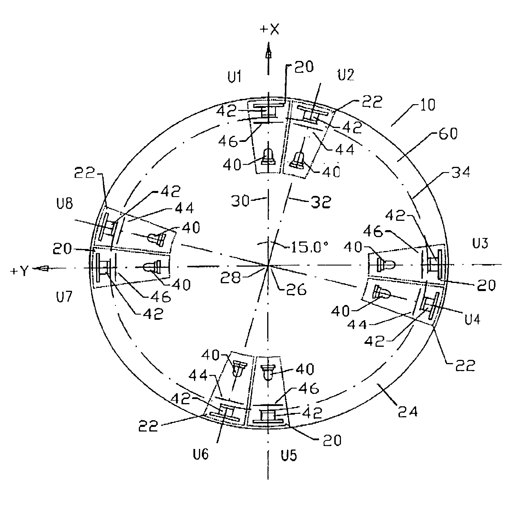
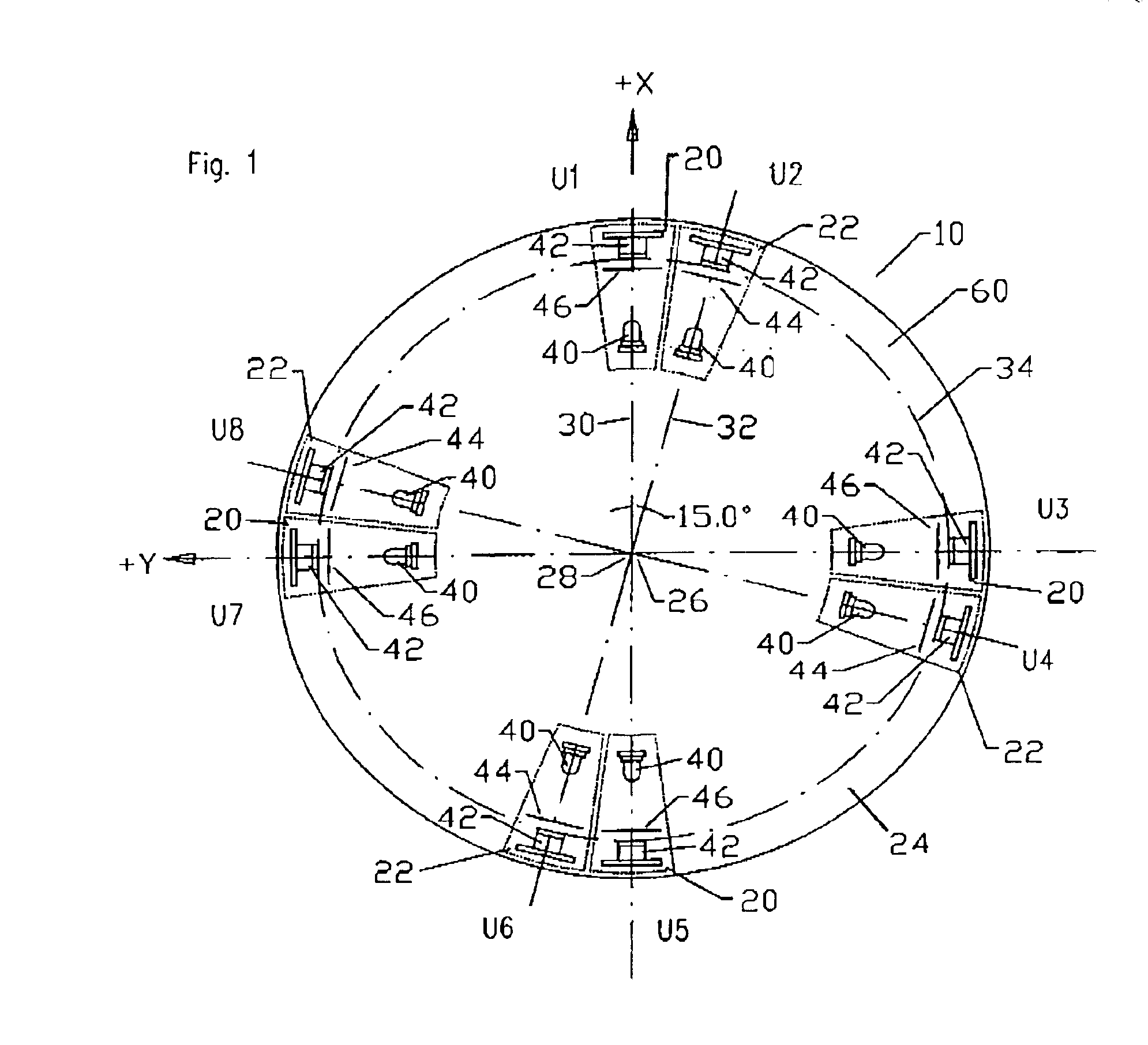
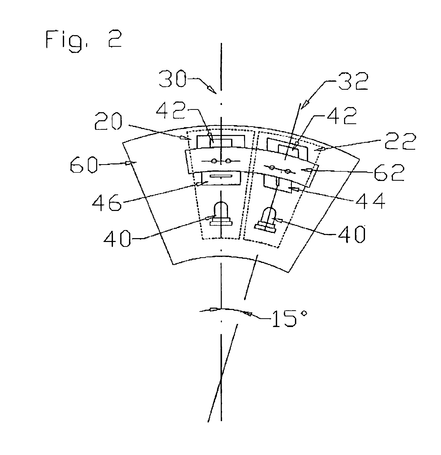
[0013]According to the present invention, however, a different approach is pursued. Instead of the usual three measuring cells, four measuring cells are employed as a vertical measuring means for the detection of a relative movement perpendicular to an imaginary plane, with the measuring cells being arranged in such a manner that their vertical projections onto the plane are arranged about a centre at an equal angular distance from each other. One would expect that this complicated solution causes higher costs than the known solution because both the nu...


PUM

PropertyMeasurementUnit
angleaaaaaaaaaa
angleaaaaaaaaaa
angleaaaaaaaaaa

Abstract

An arrangement for the detection of relative movements of two objects with four measuring cells as vertical measuring device for the detection of a relative movement perpendicular to an imaginary plane, with the measuring cells being arranged in such a manner that their vertical projections onto the plane are arranged at an identical angular distance from each other about a centre. Further, a force and / or moment sensor with a first board and a second board which are elastically connected with each other and movable relative to one another.

Description

BACKGROUND OF THE INVENTION[0001]1. Field of the Invention[0002]The present invention relates to an arrangement for the detection of relative movements of two objects as well as a force and / or moment sensor which utilizes such an arrangement. The invention further relates to potential applications for the force and / or moment sensor.[0003]2. Description of the Related Art[0004]In the state of the art, both arrangements for the detection of relative movements of two objects as well as force and moment sensors are known in a plurality of designs.[0005]DE 36 11 336 C2 discloses a force and torque sensor which measures all six possible force and torque components in the Cartesian coordinate system by means of strain gauges. The apparatus consists of two spoke wheels arranged one above the other with four spokes each and a total of 20 strain gauges which are wired with one another. The complicated design of the sensor leads to high material and construction expenses. In addition, the rigi...

Claims


Application Information

Patent Timeline
Patent Type & Authority Patents(United States)
IPC IPC(8): G01L1/04G01B11/00G01B11/16G01B21/00G01L1/26G01L5/16G01L25/00
CPCG01B11/002G01B11/16G01L5/166
Inventor MEUSEL, PETERDIETRICH, JOHANNESGOMBERT, BERND
Owner DEUTSCHES ZENTRUM FUER LUFT & RAUMFAHRT EV
Why Eureka
Try Eureka