Automatic lathe

a technology of automatic lathes and lathes, which is applied in the direction of process control, process control, instruments, etc., can solve the problems of inability to move the tools mounted at the limited type of machining which can be performed by the tools of the second tool rest, and the inability to simultaneously machine holes, etc., to achieve fast and complicated machine bars, improve the freedom of tool selection, and improve the effect of performan

Inactive Publication Date: 2005-08-16
CITIZEN WATCH CO LTD
View PDF13 Cites 32 Cited by
  • Summary
  • Abstract
  • Description
  • Claims
  • Application Information

AI Technical Summary

Benefits of technology

[0015]Therefore, an object of the present invention is to provide a high performance multifunction type automatic lathe having a plurality of spindles and a plurality of tool rests which is capable of simultaneously performing individual moti

Problems solved by technology

However, the tools mounted at the second tool rest cannot be moved by interpolation with respect to either bar held in the first and second spindles, so the type of machining able to be performed by the tools of the second tool rest is limited to end face drilling.
Further, the tools which can be simultaneously used for the first and second spindles at the second tool rest are limited to a pair of tools mounted coaxially in opposite directions to each other, so the shapes of the holes which can be simultaneously machined inevitably are limited

Method used


Image

  • Automatic lathe
  • Automatic lathe
  • Automatic lathe

Examples


Embodiment Construction

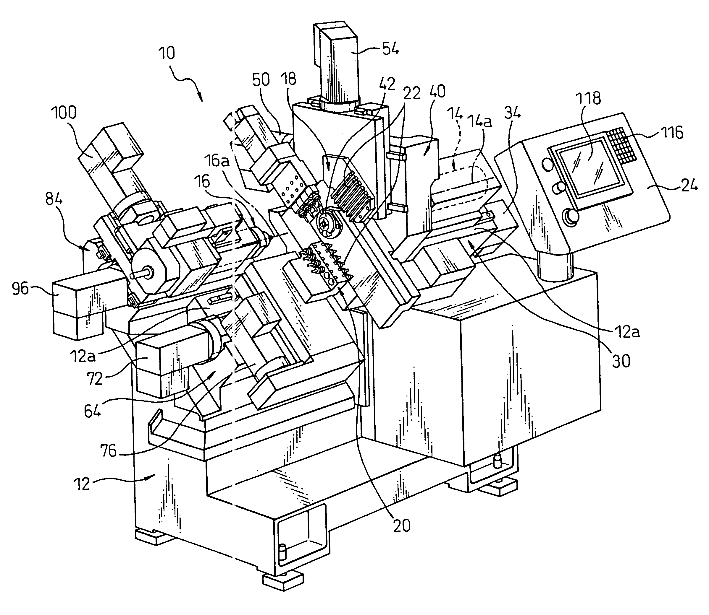
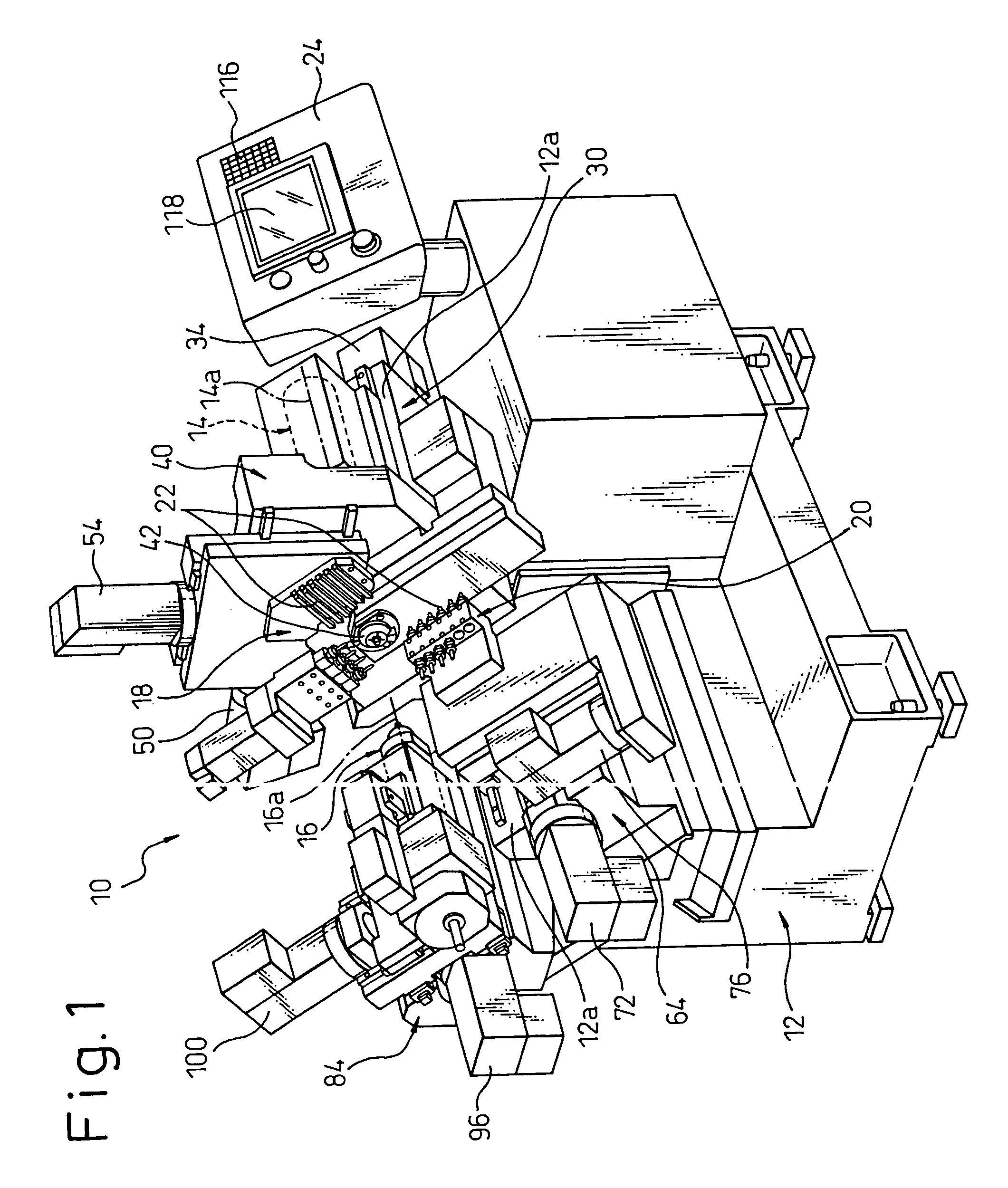
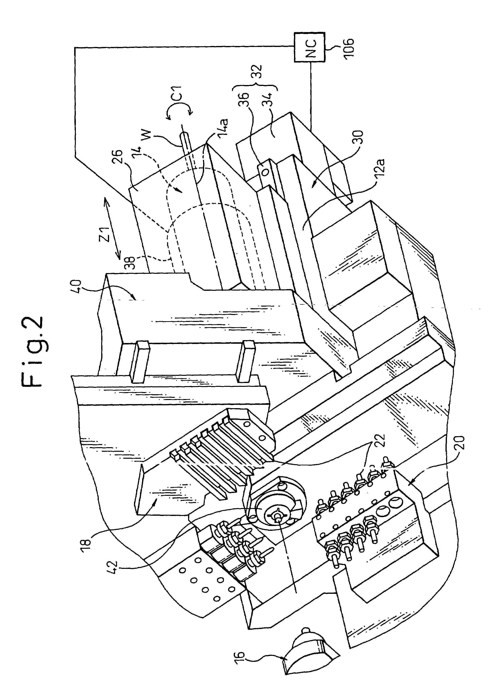
[0044]Referring to the drawings, FIG. 1 shows the overall configuration of an automatically operated or automatic lathe 10 according to an embodiment of the present invention. The automatic lathe 10 has a multifunction structure carrying close together on a single lathe bed 12 two spindles 14 and 16 and two tool rests 18 and 28 and capable of performing different types of machining (for example, outer circumferential turning and boring) simultaneously on the same bar or simultaneous machining on different bars by various tools 22 including single point tools, drills, and other turning tools or milling cutters and other rotary tools.

[0045]That is, the automatic lathe 10 is provided with a lathe bed 12; a first spindle 14 installed on the lathe bed 12 and including an axis of rotation 14a; a first tool rest 18 installed on the lathe bed 12 and capable of holding a plurality of tools 22 in a parallel arrangement; a second tool rest 20 installed on the lathe bed 12 and capable of holdin...


PUM


Abstract

An automatic lathe (10) is provided with a first spindle (14) having an axis of rotation (14a), a first tool rest (18) capable of holding a plurality of tools (22) in a parallel arrangement, a second tool rest (20) capable of holding a plurality of tools (22) in parallel arrangements in a first row and second row exhibiting mutually different nose orientations, and a second spindle (16) having an axis of rotation parallel to the axis of rotation of the first spindle and capable of being located facing the first spindle, in such a manner as to be centrally carried on a lathe bed (12). The first spindle can move linearly along a first control axis parallel to its axis of rotation. The first tool rest can move linearly along a second control axis perpendicular to the first control axis. The second tool rest can move linearly along a third control axis perpendicular to the first control axis and a fourth control axis parallel to the first control axis. The second spindle can move linearly along a fifth control axis parallel to the third control axis and a sixth control axis parallel to the first control axis. A control unit (106) enables simultaneous performance of first machining work relating to the first spindle by a desired tool selected at the first tool rest, second machining work relating to the first spindle by a desired tool selected from the first row at the second tool rest, and third machining work relating to the second spindle by a desired tool selected from the second row at the second tool rest.

Description

TECHNICAL FIELD[0001]The present invention relates to a compound machine tool capable of simultaneously or selectively performing different types of automatic machining, in particular a multifunction type automatically operated lathe carrying a plurality of spindles and a plurality of tool rests close together on a single lathe bed.BACKGROUND ART[0002]In recent years, in the field of automatically operated or automatic lathes such as numerical control (NC) lathes, to enable machining of much more complicatedly shaped workpieces from a bar-shaped worked material (hereinafter called a “bar”), compound or combination machining where a large number of types of tools including rotary tools are provided on a tool rest to enable diverse automatic machining such as milling in addition to turning is being promoted. Further, to shorten the machining time, various multifunction type automatic lathes carrying a plurality of (normally two) spindles and a plurality of (normally two to three) tool...

Claims


Application Information

Patent Timeline
IPC IPC(8): B23Q39/00B23Q39/04B23Q39/02B23B3/00B23B3/16B23B3/06B23B3/34B23B7/06B23B29/26
CPCB23B3/065B23B7/06B23B29/26B23Q39/026B23Q39/04B23Q39/048B23B3/168Y10T82/16622G05B2219/45124B23Q2230/006B23Q2039/008Y10T82/16442Y10T82/2508Y10T82/2524Y10T29/5114Y10T82/2543
Inventor AKIMOTO, SATORUSOMEYA, EIICHIROKASAHARA, SHINSUKEISHIMURA, TOSHIO
Owner CITIZEN WATCH CO LTD
Why Eureka
Try Eureka