
Transducer mounting block

Inactive Publication Date: 2005-08-16
SHANNON ALLEN T
View PDF22 Cites 17 Cited by
  • Summary
  • Abstract
  • Description
  • Claims
  • Application Information

AI Technical Summary

Benefits of technology

[0013]An important feature of the present invention is that it enables an installer to firmly and securely mount a marine transducer, or any other boltable item (e.g. a transducer plate, navigation light, or speed sensor), to a selected surface such as the transom of a boat hull with a minimum intrusion to the surface. Installation is simple with minimal time and tools.
[0014]Another feature of the present invention is that it is able to withstand marine environments by having a strong, water-resistant bond, and by being fabricated from corrosion-resistant materials.
[0015]Another feature of the present invention is that it has a minimum number of parts and material, thus anticipating low cost and high reliability.
[0016]Yet another feature of the present invention is that it allows a user to be able to remove the transducer periodically for maintenance, updates, or replacement.

Problems solved by technology

While the transom of a watercraft hull is often a convenient place to locate such sensors, few resources have been devoted to develop ways in which to attach marine transducers to transoms.
Marine environments are very harsh on watercraft and accessories.
This device requires a sealant between the transom and the bracket that is always susceptible to leakage, which can lead to hull and transom damage that is very costly to repair.
It also requires the installer to drill holes, which adds complexity to the installation process.
This arrangement limits the operation of the transducer to the low speeds where the trolling motor is operating, and it creates the potential for interference between the motor and the transducer.
The arrangement is cumbersome and may interfere with other transom-mounted devices such as outboard engines, trolling motors, and trim tabs.
The disadvantage with this invention is that it prevents the owner from using the drain hole without removing the transducer.
Furthermore, the number of transducers is proximately limited to the number of drain holes.

Method used


Image

  • Transducer mounting block
  • Transducer mounting block
  • Transducer mounting block

Examples


Embodiment Construction

[0022]The preferred embodiment of the present invention is a device that relies primarily on a mounting block with an adhesive back to enable an installer to firmly attach a marine transducer to the transom of a boat hull without drilling holes in the transom or using complicated assemblies.

[0023]An alternative embodiment of the present invention is a system wherein a mounting block with an adhesive backing cooperates with appropriately sized corrosion-resistant transducer fasteners, a transducer plate, and perhaps a transducer assembly or other boltable item. The cooperation of these components as a system or apparatus will enable the boat owner to equip his or her boat with modem sensors or boltable items without having to drill holes in the transom.

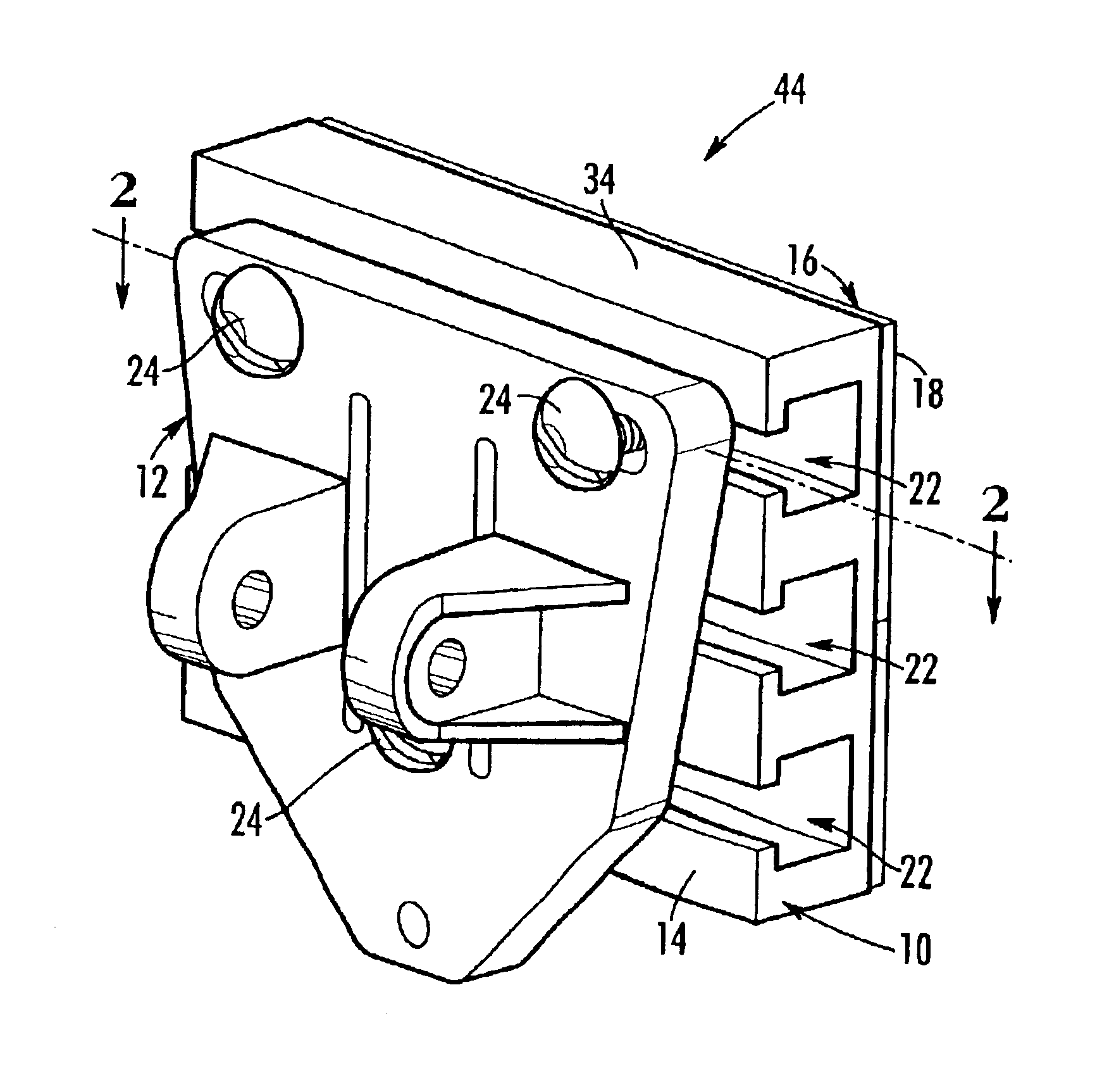
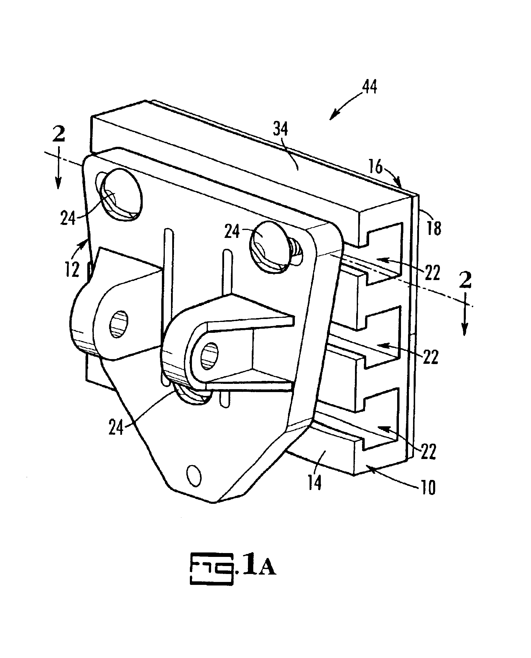
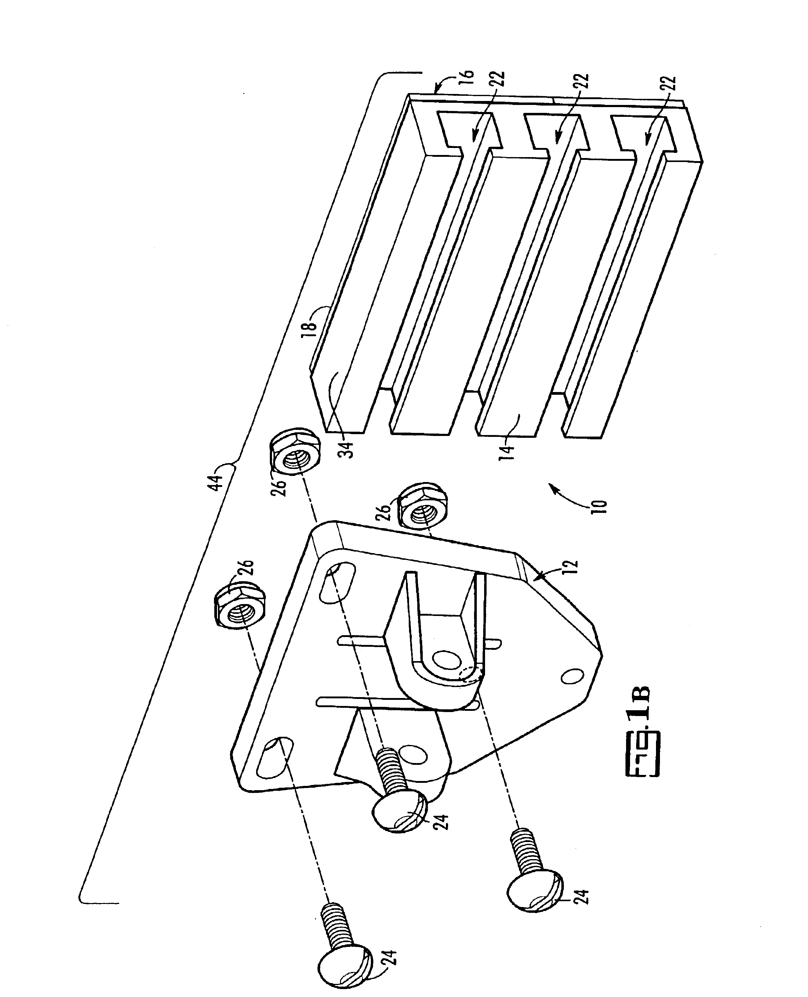
[0024]Referring now to the drawings, FIG. 1A and FIG. 1B show a mounting block 10 that is assembled to a transducer plate 12 forming a system 44 for affixing a transducer 40 to a surface 30. Transducer 40 is shown in phantom lines in F...


PUM


Abstract

A mounting system for attaching a transducer to a surface such as the transom of a boat hull is disclosed. The system consists of a mounting block, fasteners, and an item that the installer wishes to attach (such as a transducer or plate). The block is formed of corrosion-resistant material. The block has an adhesive layer that bonds the block to the surface; no fasteners are required to mount the block to the surface. The block has at least one T-shaped slot that retains corrosion-resistant fasteners, which anchor the transducer to the block when the fasteners are tightened. The adhesive layer is protected by a removable layer that is peeled away just prior to pressing the block on the transom surface.

Description

CROSS-REFERENCE TO RELATED APPLICATIONS[0001]The benefit of the filing of U.S. provisional patent application Ser. No. 60 / 373,385, filed Apr. 18, 2002, which is incorporated herein by reference, is claimed.STATEMENT REGARDING FEDERALLY SPONSORED RESEARCH OR DEVELOPMENT[0002]Not applicable.REFERENCE TO A MICROFICHE APPENDIX[0003]Not applicable.BACKGROUND OF THE INVENTION[0004]Since the inception of seafaring, humans have endeavored to attach various items to the transoms of watercraft hulls to help determine conditions both above and below the water's surface. In the last half of the twentieth century, popularity of pleasure watercraft has risen sharply. Many users of such watercraft, just as mariners of old, need assistance with navigation, operation, and locating marine quarry such as fish and wrecks.[0005]Paralleling the rise in numbers of pleasure watercraft, sensor (transducer) technology has also increased throughout the last few decades. Transducers have been produced that are...

Claims


Application Information

Patent Timeline
IPC IPC(8): B63B17/00G10K11/00
CPCB63B17/00G10K11/006B63B2221/10
Inventor SHANNON, ALLEN T.
Owner SHANNON ALLEN T
Learn More