System for connecting mounting rails

a technology of mounting rails and mounting brackets, which is applied in the direction of rod connections, key-type connections, building scaffolds, etc., can solve the problem of insufficient torsional stiffness of the connection so established, and achieve the effect of allowing for flexible arrangement arrangemen

Active Publication Date: 2005-08-16
HILTI AG
View PDF12 Cites 21 Cited by
  • Summary
  • Abstract
  • Description
  • Claims
  • Application Information

AI Technical Summary

Benefits of technology

[0005]The object of the present invention is to provide a connecting system, that has a low number of stand

Problems solved by technology

The drawback in the known solution is that the attachment members can be fastened to the base members only in the position predefined by the snap-in and complementary snap-in members.
If the

Method used


Image

  • System for connecting mounting rails
  • System for connecting mounting rails
  • System for connecting mounting rails

Examples


Embodiment Construction

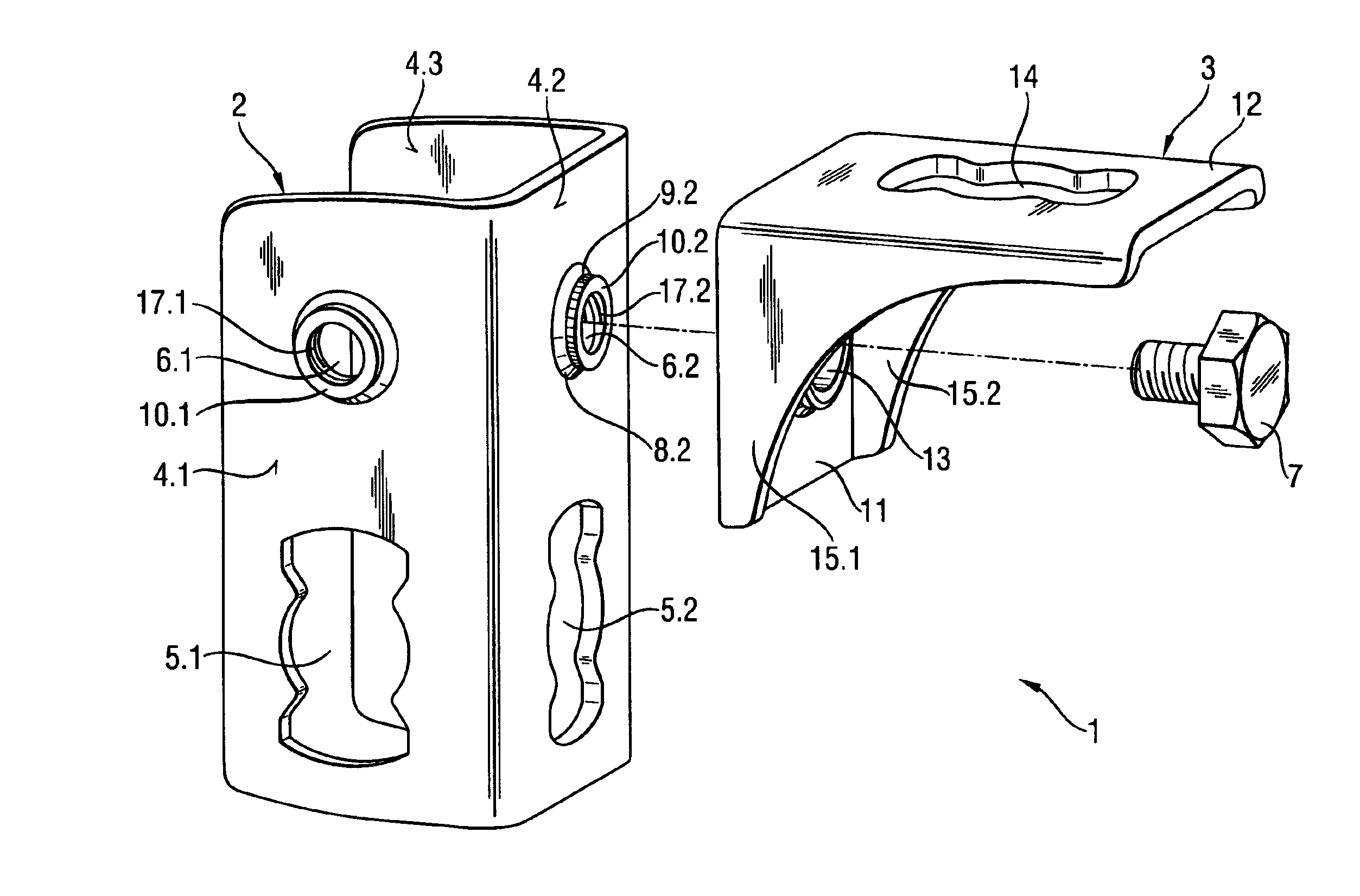
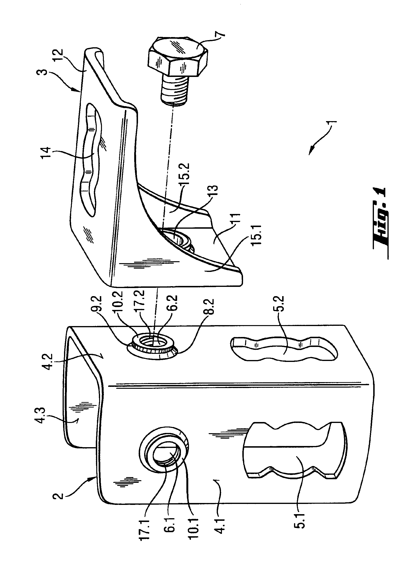
[0020]FIG. 1 represents an exploded view of the system according to the invention having a base member and an attachment member. The connection system 1 comprises a U-shaped base member 2 and an angular attachment member 3. The base member 2 is manufactured from a higher-strength material than the attachment member 3.

[0021]The base member 2 has openings 5.1, 5.2 or 5.3 on all three lateral walls 4.1, 4.2 and 4.3 for passage therethrough of a rail bolt for fastening the base member 2 to a first mounting rail. Preferably, so called quick-check bolts are used, as are commonly used in pipeline installations in conjunction with mounting rails. Furthermore, an opening 6.1, 6.2 or 6.3 having an inner thread 17.1, 17.2 or 17.3 is provided on each lateral wall 4.1, 4.2 and 4.3 and into which the fastener, the bolt 7 for example, can engage for fastening the attachment member 3 to the base member 2. The openings 6.1, 6.2, and 6.3 have a collar 10.1, 10.2, and 10.3 that has a conical section 8...


PUM


Abstract

A system (1) for connecting mounting rails comprises a base member (2) and an angular attachment member (3). The base member (2) has an opening (6.1, 6.2) in at least one lateral wall (4.1, 4.2 or 4.3) for passage therethrough of a bolt (7). The openings (6.1, 6.2) are each provided with a collar (10.1, 10.2), which can be brought into engagement with the opening (13) in the attachment member (3). The collar (10.1, 10.2) has at least in an axial region a conical section (8.2) shaped as a clamping cone. At the time of tightening the bolt 7, a form- and force-locking connection between the base member (2) and the attachment member (3) is created.

Description

TECHNICAL FIELD[0001]The invention relates to a system for connecting mounting rails, in particular for connecting C-shaped mounting rails, wherein the system comprises a base member and at least one substantially angular attachment member. The base member has in at least one lateral wall an opening, which is provided with a collar, for passage therethrough of a fastener. An attachment member has an opening for passage therethrough of the fastener, wherein the collar can be brought into engagement with the at least one opening in the attachment member.PRIOR ART[0002]Conduit installations are, for example, fastened to mounting rails that are arranged on a ceiling. For installation of conduit line arrangements erected in space are also used, which are generally comprised of individual standardized sections. Such arrangements are, for example, assembled from a plurality of interconnected C-shaped mounting rails. A variety of systems for connecting mounting rails is known, which make po...

Claims


Application Information

Patent Timeline
IPC IPC(8): F16B3/06F16B3/00F16B7/18
CPCF16B3/06F16B7/18Y10T403/1616Y10T403/4966Y10T403/49Y10T403/1624Y10T403/4941
Inventor HOFMANN, ARMINHERB, ARMINUNVERZAGT, STEFAN
Owner HILTI AG
Why Eureka
Try Eureka