
Plenum fan banding

a technology of plenum fans and plenum fans, which is applied in the direction of liquid fuel engines, marine propulsion, vessel construction, etc., can solve the problems of variable speed drive motors that are more expensive to install, variable speed drive motors that are more expensive to service, and process that is expensive and time-consuming

Inactive Publication Date: 2005-08-16
AAON
View PDF17 Cites 19 Cited by
  • Summary
  • Abstract
  • Description
  • Claims
  • Application Information

AI Technical Summary

Benefits of technology

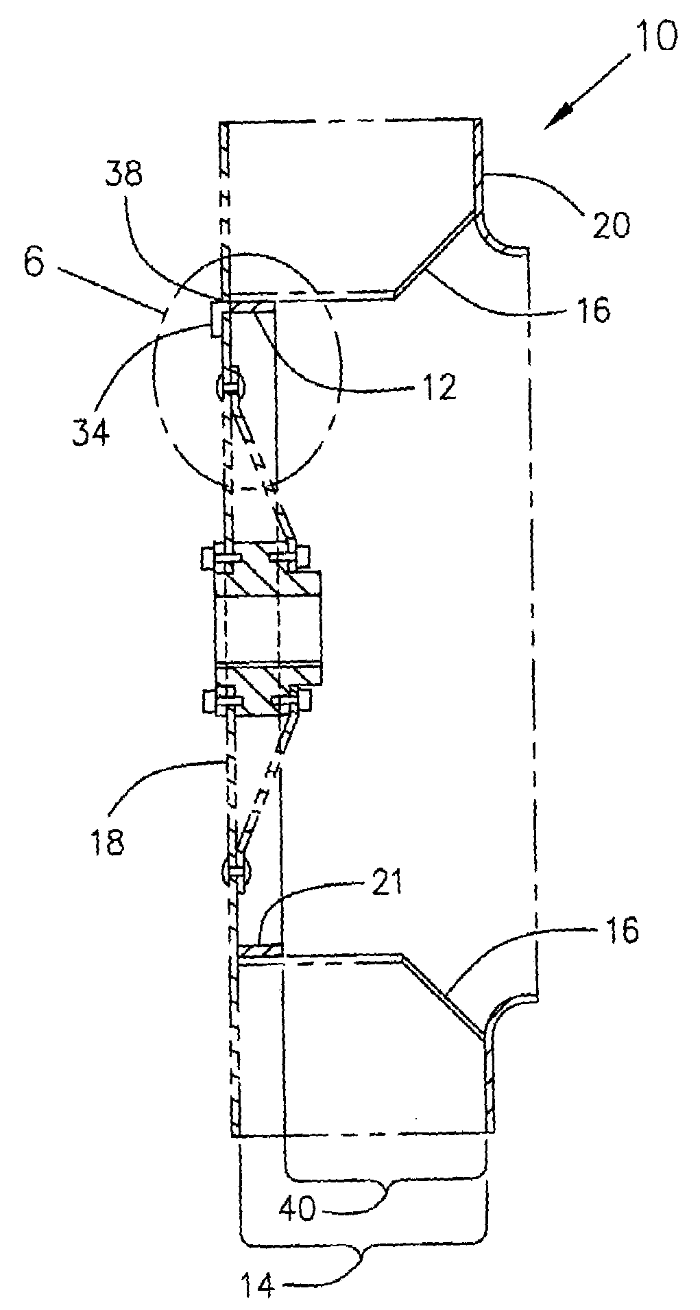
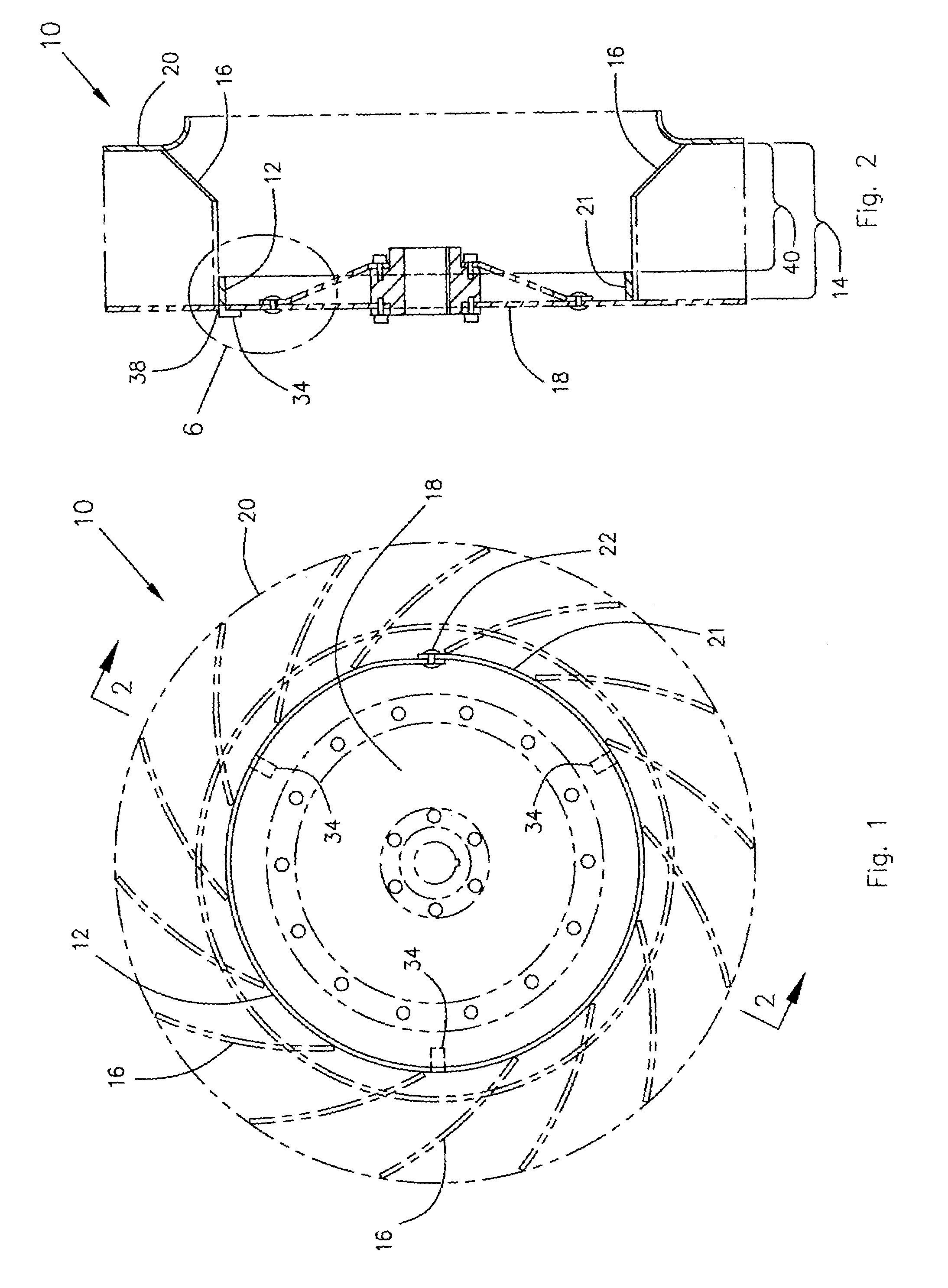
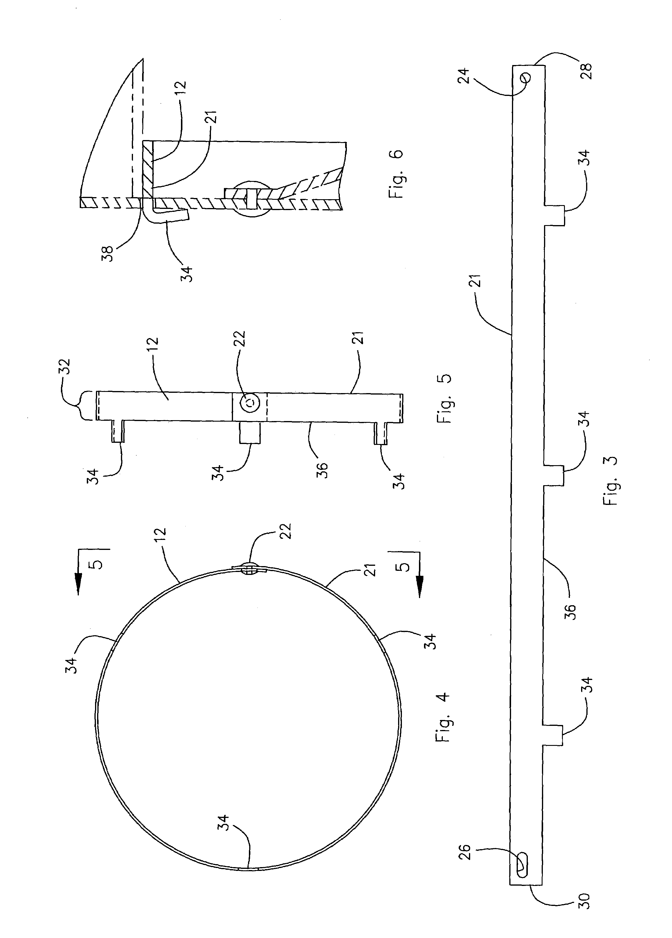
[0011]The present invention is plenum fan banding that effectively changes the width of the fan blades without having to replace the fan or made major modifications to it. The present invention employs a removable and replaceable band that attaches to the back of a fan wheel so that the band extends outward perpendicular to the back of the wheel. This band is preferably constructed of a strip of sheet metal that is fastened together at its ends with rivets or other suitable fasteners to form a hoop that is of a uniform desired width. Several tabs are provided on one edge of the strip so that when that edge of the strip is facing the back of the fan wheel, the tabs can be inserted through slots provided in the back of the fan wheel as a means of securing the band to the fan wheel.
[0012]Once the tabs are fully inserted in their respective slots, the tabs are bent over, thereby holding the band securely to the fan wheel. When thus attached to the fan wheel, the band extends perpendicular to the back of the fan wheel and is located inside or within the circle of fan blades. By attaching the band to the fan wheel in this manner, the band changes the effective width of the fan wheel, thereby allowing the output of the fan, which is direct driven by a single speed motor, to be finely adjusted or trimmed to match the performance of the HVAC unit in which it is employed.
[0013]Also, because the band is attached by tabs to the back of the fan, by simply straightening the tabs back out, the tabs can be removed from the slots to thereby remove the band from the fan. This allows the band to be replaced by another band of a different width to thereby change the effective width of the fan blades and adjust the resulting output of the plenum fan.

Problems solved by technology

A variable speed drive motor is more expensive to install than a single speed drive motor and a variable speed drive motor is more expensive to service.
This requires that the wheel be replaced with another wheel of a different width, a process that is expensive and time consuming.
Each of these methods has its own unique problems.

Method used


Image

  • Plenum fan banding
  • Plenum fan banding
  • Plenum fan banding

Examples


Embodiment Construction

Invention

[0020]Referring now to the drawings and initially to FIGS. 1 and 2, there is illustrated a plenum fan 10 with a band 12 that is constructed in accordance with a preferred embodiment of the present invention. The plenum fan banding 12 effectively changes the width 14 of the fan blades 16 without having to replace the fan blades 16 or made major modifications to the fan 10. The present invention employs a removable and replaceable band 12 that attaches to the back 18 of a plenum fan wheel 20 so that the band 12 extends outward perpendicular to the back 18 of the wheel 20. The fan wheel 20 is comprised of the back 18 and a circle of fan blades 16 that are attached to the back 18, as illustrated in FIGS. 1 and 2.

[0021]As illustrated in FIGS. 3, 4 and 5, the band 12 is preferably constructed of a strip 21 of sheet metal that is fastened together at its two opposite ends 28 and 30 with rivets 22 or other suitable fasteners that insert through openings 24 and 26 provided in the en...


PUM


Abstract

Plenum fan banding that effectively changes the width of the fan blades in a plenum fan for a HVAC unit. A removable and replaceable band attaches to the back of a fan wheel of the plenum fan so that the band is located within the circle of the fan blades and extends outward perpendicular to the back of the wheel. The band is provided with tabs that insert through slots provided in the back of the fan wheel, and the tabs can be bent over as a means of removably securing the band to the fan wheel. The band effective reduces the functional width of the fan blades in proportion to the width of the band.

Description

BACKGROUND OF THE INVENTION[0001]1. Field of the Invention[0002]The present invention relates to a plenum fan banding. More specifically the present invention employs a removable and replaceable band that attaches to the back of a fan wheel so that the band extends outward perpendicular to the back of the wheel. Addition of the band to the back of the fan wheel changes the effective width of the fan wheel, thereby allowing the output of the fan, which is direct driven by a single speed motor, to be finely adjusted or trimmed to match the performance of the HVAC unit in which it is employed.[0003]2. Description of the Related Art[0004]It is desirable to match the performance of a plenum fan to the performance of the HVAC unit with which the fan is employed. Currently, there are two methods that are commonly employed to fine adjust or trim the plenum fan so that its performance can be matched to that of its associated HVAC unit.[0005]The first of these two current methods for trimming...

Claims


Application Information

Patent Timeline
IPC IPC(8): F04D29/28
CPCF04D29/281Y10S415/912
Inventor PARGETER, STEPHEN J.STOCKTON, BRENT
Owner AAON
Learn More