Body coil for magnetic resonance imaging

a body coil and magnetic resonance imaging technology, applied in the direction of magnetic variable regulation, process and machine control, instruments, etc., can solve the problems of increasing scanning time, loss of internal space of the cylinder, and increasing the frequency power applied, so as to reduce the local specific absorption rate of radio frequency induced by the magnetic field, increase the effective action width of the current, and reduce the effect of local specific absorption ra

Active Publication Date: 2017-02-14
SIEMENS HEALTHCARE GMBH
View PDF12 Cites 0 Cited by
  • Summary
  • Abstract
  • Description
  • Claims
  • Application Information

AI Technical Summary

Benefits of technology

[0018]Since in the end ring of the body coil, the effective action width of the current is increased in the axial direction and the centralized flow of the current in the end ring is reduced, the local specific absorption rate of radio frequency induced by the magnetic field is therefore reduced.

Problems solved by technology

Since specific absorption rate is in proportion to the square of the field intensity, specific absorption rate is a critical problem in a magnetic resonance imaging system with a high field intensity.
Relatively high local specific absorption rate means that the average radio frequency power applied to the body coil is to be limited, but the limiting will increase the scanning time.
In a high-pass bird-cage body coil structure, the worst situation is where the local specific absorption rate of radio frequency is located near the end ring.
All the above-mentioned methods are on the basis of reducing electric field coupling, but these methods have problems such as high costs, loss of internal space of the cylinder, and so on.
Moreover, if the local specific absorption rate is dominated by the magnetic field, the above-mentioned methods may not have the desired effects.

Method used


Image

  • Body coil for magnetic resonance imaging
  • Body coil for magnetic resonance imaging
  • Body coil for magnetic resonance imaging

Examples


first embodiment

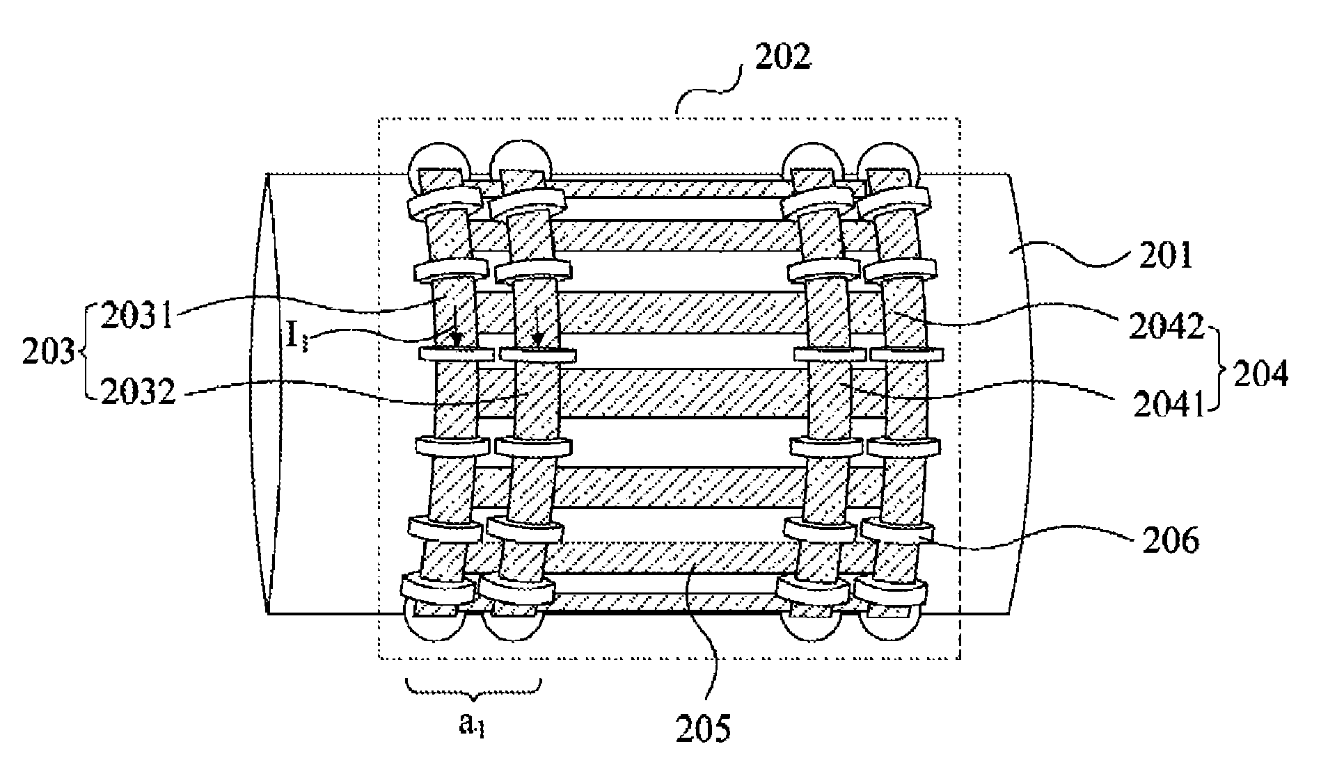
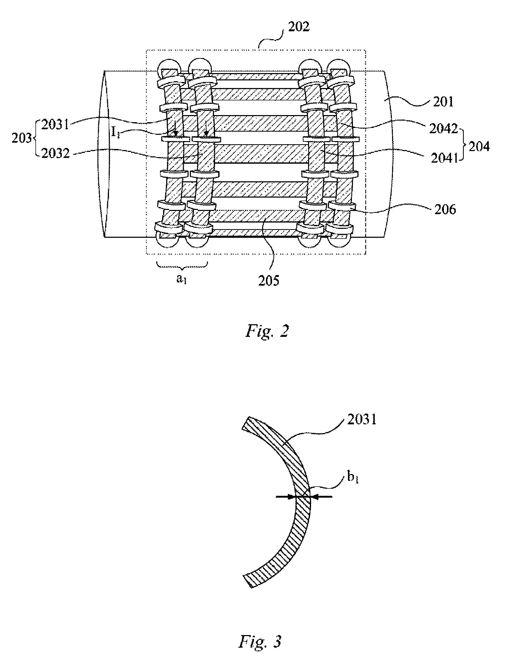
[0029]FIG. 2 is a schematic diagram of a body coil having an end ring structure according to a As shown in FIG. 2, reference numeral 201 indicates a cylinder for housing a patient in magnetic resonance imaging equipment. 202 indicates a body coil for emitting an electromagnetic field to the cylinder 201. The body coil 202 is provided outside the cylinder 201 in the axial direction. The body coil 202 has a double number of end rings (i.e., at two ends of the body coil 202, each end has a group of end rings 203 (first end rings) and 204 (second end rings), while each group of end rings 203 and 204 respectively has two parallel rings 2031, 2032 and 2041, 2042). In this embodiment, there are intervals among these end rings 203, 204. Feed points are provided on two groups of end rings 203 and 204 for exciting a required electromagnetic field. In this embodiment, since the number of end rings 203, 204 is increased in the axial direction of the body coil 202, the width a1 of the current I...

second embodiment

[0037]FIG. 4 is a schematic diagram of a body coil having an end ring structure according to a As shown in FIG. 4, reference numeral 401 indicates a cylinder for housing a patient in magnetic resonance imaging equipment. 402 indicates a body coil, and the body coil 402 is provided outside the cylinder 301 in the axial direction. The body coil 402 has a structure with a triple number of end rings (i.e., at two ends of the body coil 402, each end has a group of end rings 403 (first end rings) and 404 (second end rings), while each group of end rings 403 and 404 respectively has three parallel rings 4031, 4032, 4033, and 4041, 4042, 4043). In this embodiment, there are intervals among these end rings. Feed points are provided on two groups of end rings 403 and 404 for exciting a required electromagnetic field.

[0038]In this embodiment, since the number of end rings is increased in the axial direction of the body coil 402, the width a2 of the current I2 of the first end ring 403 and the...

third embodiment

[0048]FIG. 5 is a schematic diagram of a body coil having an end ring structure according to a As shown in FIG. 5, reference numeral 501 indicates a cylinder for housing a patient in magnetic resonance imaging equipment. 502 indicates a body coil for exciting an electromagnetic field, and the body coil 502 is provided outside the cylinder 501 in the axial direction. The body coil 502 has an end ring 503 (first end ring) and an end ring 504 (second end ring), which are respectively located at either end of the body coil 502. The widths of the first end ring 503 and the second end ring 504 in the axial direction are increased by a predetermined size or multiple (e.g., increased by once, twice, triple, or more). For example, in the conventional technology, the width of the end ring is set to be about 50 mm, but in some embodiments, the width of the end ring is set as about 75 mm, 100 mm, 125 mm, 150 mm, 175 mm, 200 mm, etc., or even wider. A feed point is provided on two end rings 403...


PUM


Abstract

A body coil includes a first end ring and a second end ring provided at two ends thereof. The first end ring and the second end ring are connected to each other with a plurality of legs. The first end ring or the second end ring has a structure with the current flow width in a direction parallel to the axis thereof being greater than that in a direction perpendicular to the axis thereof. Since the effective action width of the current is increased in the axial direction and the centralized flow of the current in the end ring is reduced, the local specific absorption rate of radio frequency induced by the magnetic field is therefore reduced.

Description

RELATED APPLICATIONS[0001]This application claims the benefit of Chinese Patent Application No. CN 201210413910.3, filed Oct. 25, 2012, the entire contents of which are hereby incorporated herein by reference.TECHNICAL FIELD[0002]The present embodiments relate to the field of magnetic resonance imaging equipment, and particularly, to a body coil for applying an electromagnetic field used in magnetic resonance imaging equipment.BACKGROUND[0003]In a magnetic resonance imaging (MRI) system, specific absorption rate (SAR) is a safety indicator. Since specific absorption rate is in proportion to the square of the field intensity, specific absorption rate is a critical problem in a magnetic resonance imaging system with a high field intensity. A body coil is a critical component for transferring energy. Relatively high local specific absorption rate means that the average radio frequency power applied to the body coil is to be limited, but the limiting will increase the scanning time. Hen...

Claims


Application Information

Patent Timeline
Patent Type & Authority Patents(United States)
IPC IPC(8): G01R33/34G01R33/28
CPCG01R33/34076G01R33/288G01N24/00A61B5/055
Inventor CHEN, YAN LITANG, YUVESTER, MARKUSWANG, JIAN MINLI, ZHIBIN
Owner SIEMENS HEALTHCARE GMBH
Why Eureka
Try Eureka