Combined electrical connector and radiator for high current applications

Inactive Publication Date: 2005-08-16
SYLVA INDS
View PDF12 Cites 70 Cited by
  • Summary
  • Abstract
  • Description
  • Claims
  • Application Information

AI Technical Summary

Benefits of technology

[0013]In view of the afore-said, it is therefore an object of the present invention to provide improved electrical connectors which have improved heat dissipation characteristics to slow down the building up of adverse heat while at the same time with minimal, insignificant, or even nil additional costs, weight or volume overheads. Put simply, it is an object of the present invent

Problems solved by technology

However, larger cross-sectional area means heavier and more costly connectors which are undesirable or even un-acceptable for many applications.
Furthermore, excessive temperature will cause the rigid connector bar to expand which may cause distortion, or even damage, to the term

Method used


Image

  • Combined electrical connector and radiator for high current applications
  • Combined electrical connector and radiator for high current applications
  • Combined electrical connector and radiator for high current applications

Examples


Embodiment Construction

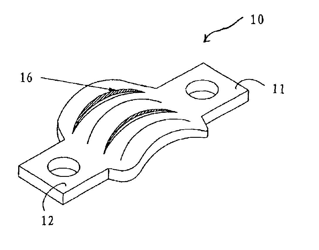
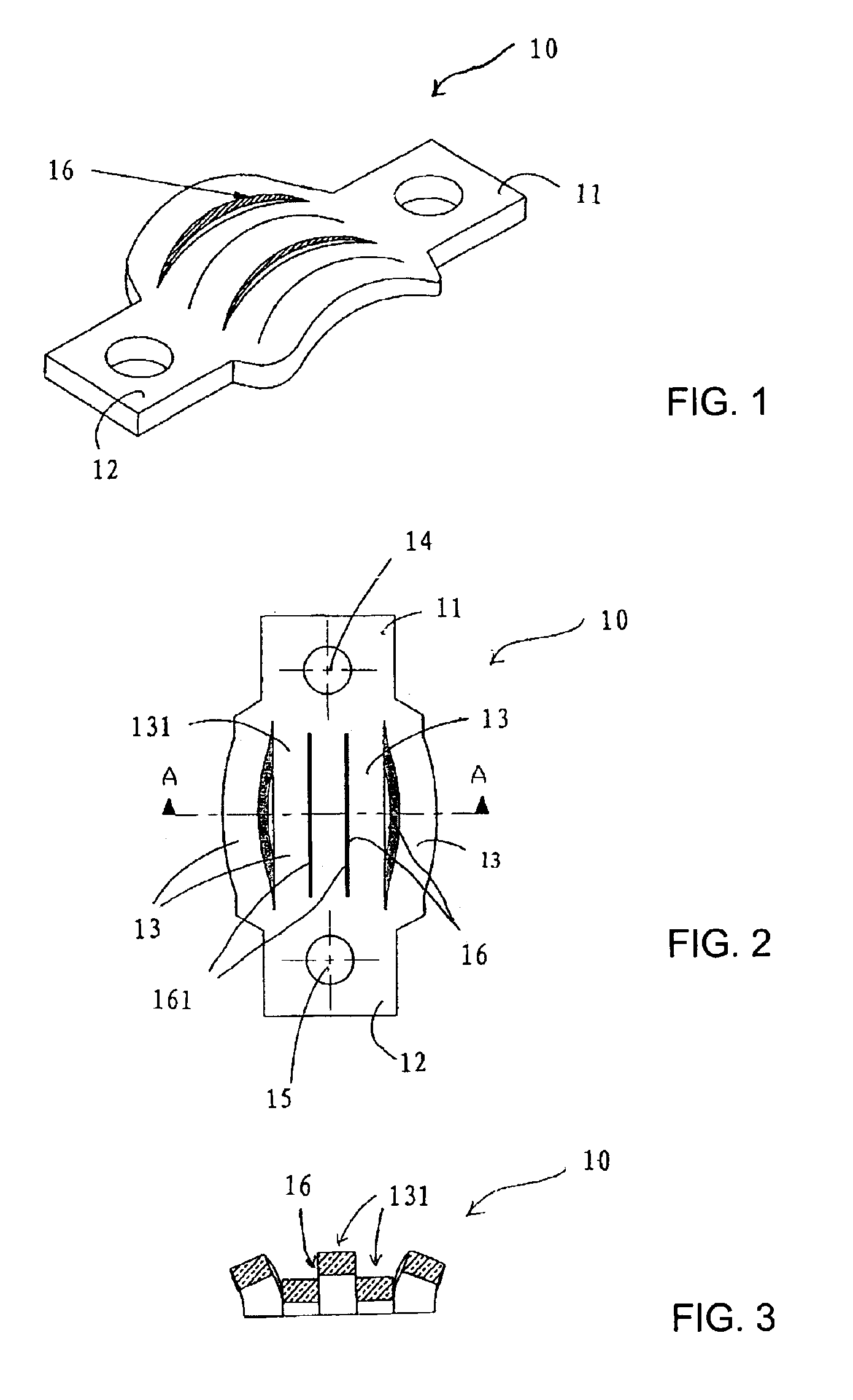
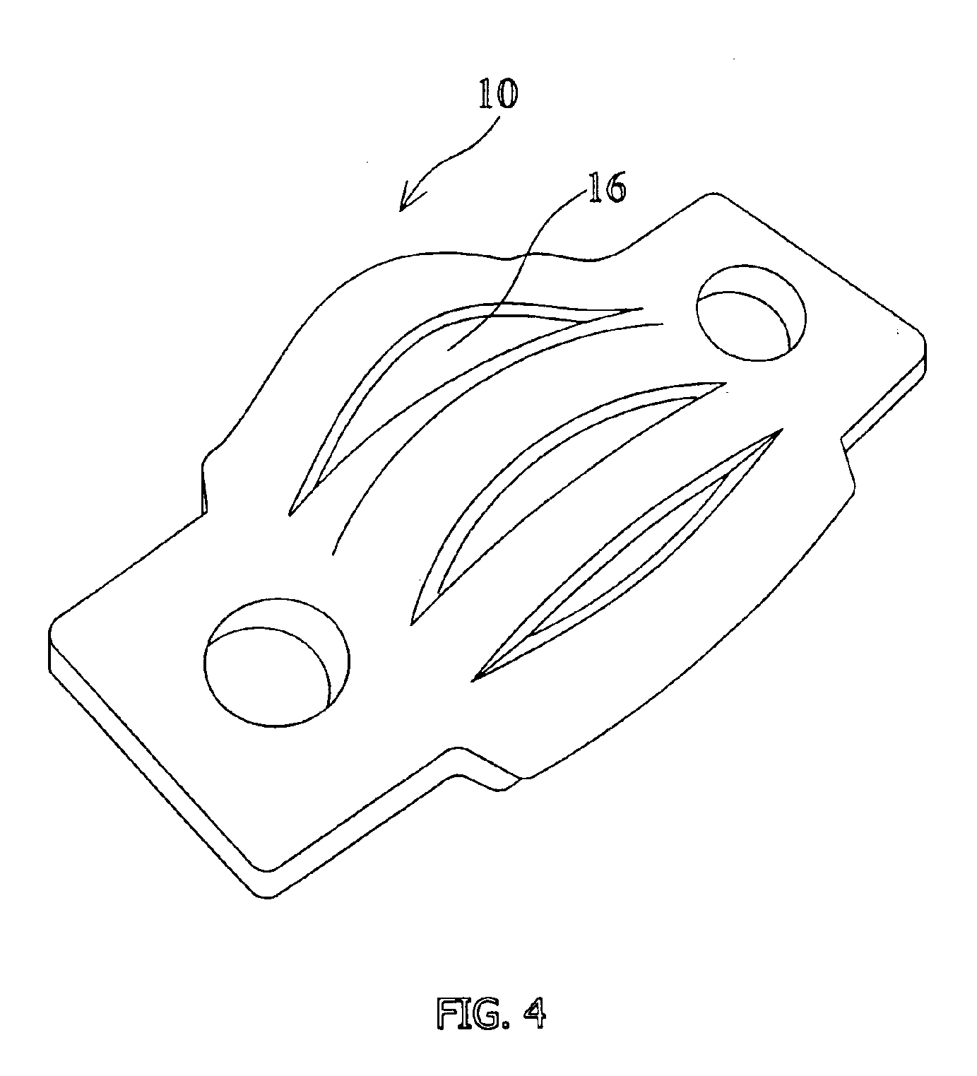
[0044]Referring firstly to FIGS. 1-4, there is shown a first preferred embodiment of an improved electrical connector (10) of the present invention. The connector includes a first (11) and a second (12) conductive terminals which are interconnected by a plurality of elongated conductive strips (13) as shown in FIGS. 2 and 3. At least a plurality of the elongated conductive strips (13) are substantially parallel to the general direction of current flow which is generally the same as the line joining the two terminals (11, 12). An aperture (14, 15) or air-gap is formed on each of the connector terminals for fastening to corresponding terminals of the adjacent electric circuit or, in the case of accumulators, adjacent cells. The generally parallel elongated conductive strips are separated by elongate air slots, aperture, or air gaps (16, 161).

[0045]At least some of the air slots or gaps (161) are also generally parallel to the line joining the two terminals. The elongated air gaps or s...


PUM


Abstract

An electrical connector useful for both high-current and low-current applications including a first and a second conductive terminals, in which the terminals are interconnected by a plurality of substantially rigid and elongated conductive strips and apertures or gaps are disposed between at least some of the adjacent conductive strips. The connector provides enhanced heat dissipation characteristics and is particularly useful for high current applications such as for connecting batteries, accumulators, super-capacitors and the like storage power units for electric vehicle and other applications.

Description

FIELD OF THE INVENTION[0001]The present invention relates to electrical connectors and, more particularly, to electrical connectors with enhanced heat radiating characteristics for high current applications. More specifically, although of course not solely limiting thereto, this invention relates to heat radiating electrical connectors for use in inter-cell and inter-battery electrical connections and especially in a high current environment. In addition, this invention also relates to batteries, battery groups or other storage power devices using connectors described in the following specification.BACKGROUND OF THE INVENTION[0002]In many electrical devices, apparatus and systems, electrical connectors are essentially used to enable circuit inter-connections and therefore to provide complete electrical power circuits. In many electrical applications, for example, electric vehicles, in which a high current supply is required, electrical connectors are used to provide sufficient curre...

Claims


Application Information

Patent Timeline
IPC IPC(8): H01R11/28H01R11/11H01M50/503H01M50/522
CPCH01M2/202H01M2/206H01R11/288Y02E60/10H01M50/522H01M50/503
Inventor LING, PUI TSANG PETERTONG, YIU SING
Owner SYLVA INDS
Why Eureka
Try Eureka