
Position detector and position indicator therefor

a position indicator and detector technology, applied in the field of position indicators, can solve the problems of inability to obtain the correct continuous quantities, inability to accurately detect writing forces, and decrease in sampling rate, so as to achieve accurate detection, reduce cost, and improve the effect of position indicators

Inactive Publication Date: 2005-08-16
WACOM CO LTD
View PDF4 Cites 23 Cited by
  • Summary
  • Abstract
  • Description
  • Claims
  • Application Information

AI Technical Summary

Benefits of technology

[0013]Accordingly, it is an object of the present invention to provide a position detector and a position indicator therefor for accurately detecting a continuous quantity in accordance with an operation, at a low cost, without causing the structure of the position indicator to become complex.
[0014]It is another object of the present invention to provide a position detector and a position indicator therefor for accurately detecting a continuous quantity in accordance with an operation at a fast sampling rate.
[0018]According to the present invention, even when the level and phase of a signal vary because of the height and tilt of a position indicator, a continuous quantity in accordance with an operation can be accurately detected. Also, detection of a single continuous quantity and the maximum reference value and the minimum reference value of the continuous quantity can each be performed by one transmission / reception. As a result, a continuous quantity in accordance with an operation can be accurately detected at a high sampling rate.

Problems solved by technology

It is thus impossible to accurately detect writing forces.
It is thus impossible to obtain the correct continuous quantities.
The position indicator has another disadvantage in that the sampling rate decreases due to the necessity for repeating transmission / reception for each bit because a single continuous quantity is transmitted back in terms of binary code.

Method used


Image

  • Position detector and position indicator therefor
  • Position detector and position indicator therefor
  • Position detector and position indicator therefor

Examples


first embodiment

Extended First Embodiment

[0059]Although a variable resistor formed of pressure-sensitive conductive rubber has been used to detect a continuous quantity, the present invention can be implemented by other methods.

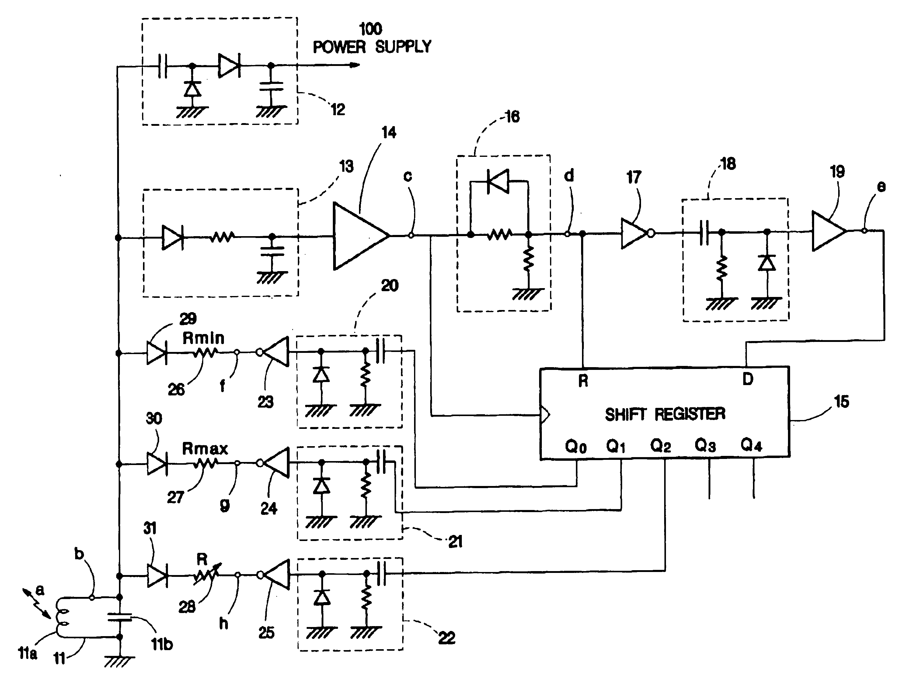
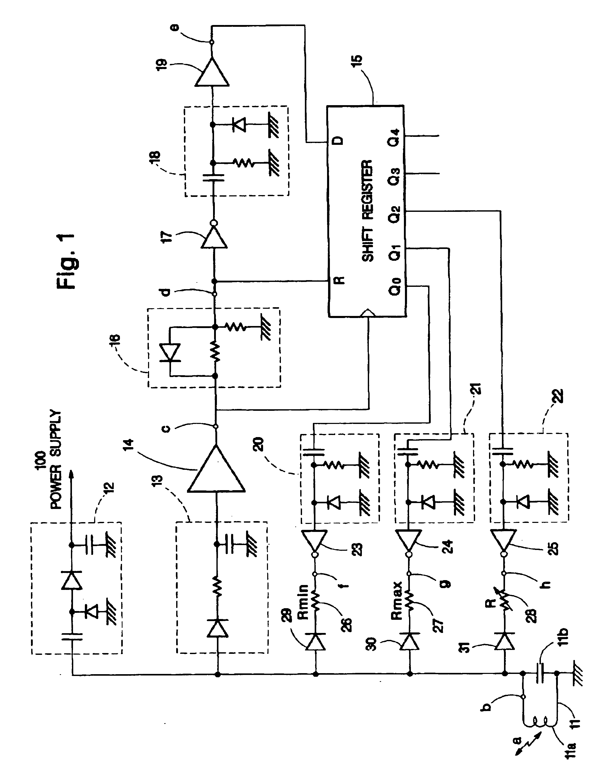
[0060]When a load of 0 g is applied to the variable resistor 28, the resistance of the variable resistor 28 becomes substantially maximum. In such a case, the differentiating circuit 21, the inverter 24, the resistor 27, and the diode 30 in the position indicator, and the second transmission / reception during the writing force detecting period can be omitted, and the reception level immediately after the continuous transmission can be used as Vb.

Second Embodiment

Structure of Second Embodiment

[0061]FIG. 5 shows the structure of a position indicator according to a second embodiment of the present invention. Referring to FIG. 5, the same reference numerals are given to components corresponding to those in the first embodiment. The structure shown in FIG. 5 differs from that of t...

second embodiment

Extended Second Embodiment

[0079]Although analog switches are used to connect the capacitors 64 and 65 and the variable capacitor 66 to the resonant circuit 11, the capacitors 64 and 65 and the variable capacitor 66 can be connected to the resonant circuit 11 through diodes instead, as in the first embodiment.

[0080]Although the output value of the integrating amplifier 73 decreases as the electrostatic capacitance of the variable capacitor 66 increases, the synchronous detector 71 can be configured in order that this relationship can be reversed.

Third Embodiment

Structure of Third Embodiment

[0081]FIG. 8 shows the structure of a position indicator according to a third embodiment of the present invention. Referring to FIG. 8, the same reference numerals are given to components corresponding to those in the first embodiment.

[0082]Referring to FIG. 8, the coil 11a and the capacitor 11b form the resonant circuit 11 which resonates at the predetermined frequency fo. The power supply circuit...

third embodiment

Extended Third Embodiment

[0111]In the third embodiment, the resistors each having the resistance RAmin are connected in series with the variable resistors 85 to 87, respectively, and hence the reference value when the dial setting is minimum is commonly used as V1 which is the reference value for detecting the writing force. Alternatively, resistors having different resistances can be employed, and reference values can be computed at different times.


PUM


Abstract

A position indicator contains a resonant circuit. A first resistor having a minimum resistance, a second resistor having a maximum resistance, and a variable resistor whose resistance varies within the range of minimum to maximum resistances are connected to the resonant circuit at first, second, and third specific times based on predetermined timing information supplied from a tablet. Signal levels detected by the tablet at the first and second specific times are used as a lower limit and an upper limit of an operation quantity. Within this range, a signal level detected at the third specific time is converted into an operation quantity. Thus, the continuous quantity can be detected at a fast sampling rate without being influenced by the height and tilt of the position indicator.

Description

BACKGROUND OF THE INVENTION[0001]1. Field of the Invention[0002]The present invention relates to position detectors and position indicators therefor for use in inputting graphics and characters to computers.[0003]2. Description of the Related Art[0004]One type of known position detector is disclosed in Japanese Unexamined Patent Application Publication No. Kokai Hei 1-53223 (earlier patent application 1)(U.S. Pat. No. 5,134,689).[0005]In this position detector, a position indicator is provided with a resonant circuit containing a coil and a capacitor. Electromagnetic waves are transmitted between a tablet and the position indicator, whereby coordinate values of a position indicated by the position indicator are detected. Of a plurality of loop coils which are provided in the tablet and which are parallel to position detecting directions, the loop coils are sequentially selected, and the selected loop coil emits electromagnetic waves. The electromagnetic waves which are reemitted fro...

Claims


Application Information

Patent Timeline
Patent Type & Authority Patents(United States)
IPC IPC(8): G06F3/033G06F3/046
CPCG06F3/03545G06F3/046
Inventor KATSURAHIRA, YUJI
Owner WACOM CO LTD
Features
  • Generate Ideas
  • Intellectual Property
  • Life Sciences
  • Materials
  • Tech Scout
  • Unparalleled Data Quality
  • Higher Quality Content
  • 60% Fewer Hallucinations
Learn More