
Power reduction

a power reduction and power technology, applied in the field of power reduction, can solve the problems of reducing the overall bit error ratio of the transmission, generating broadband noise, data loss, etc., and achieve the effect of reducing the crest factor of the signal

Inactive Publication Date: 2005-08-16
AVAGO TECH INT SALES PTE LTD
View PDF5 Cites 15 Cited by
  • Summary
  • Abstract
  • Description
  • Claims
  • Application Information

AI Technical Summary

Benefits of technology

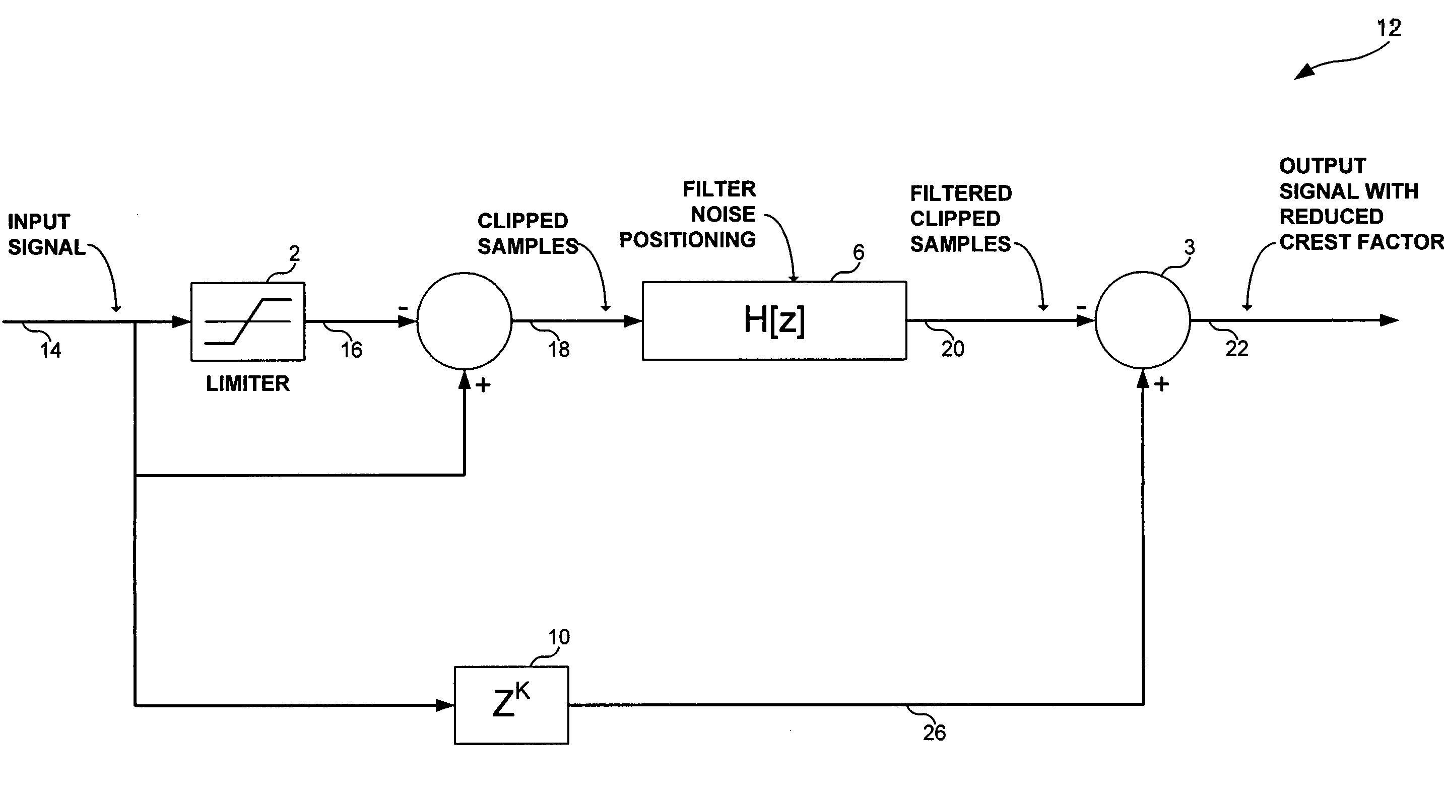
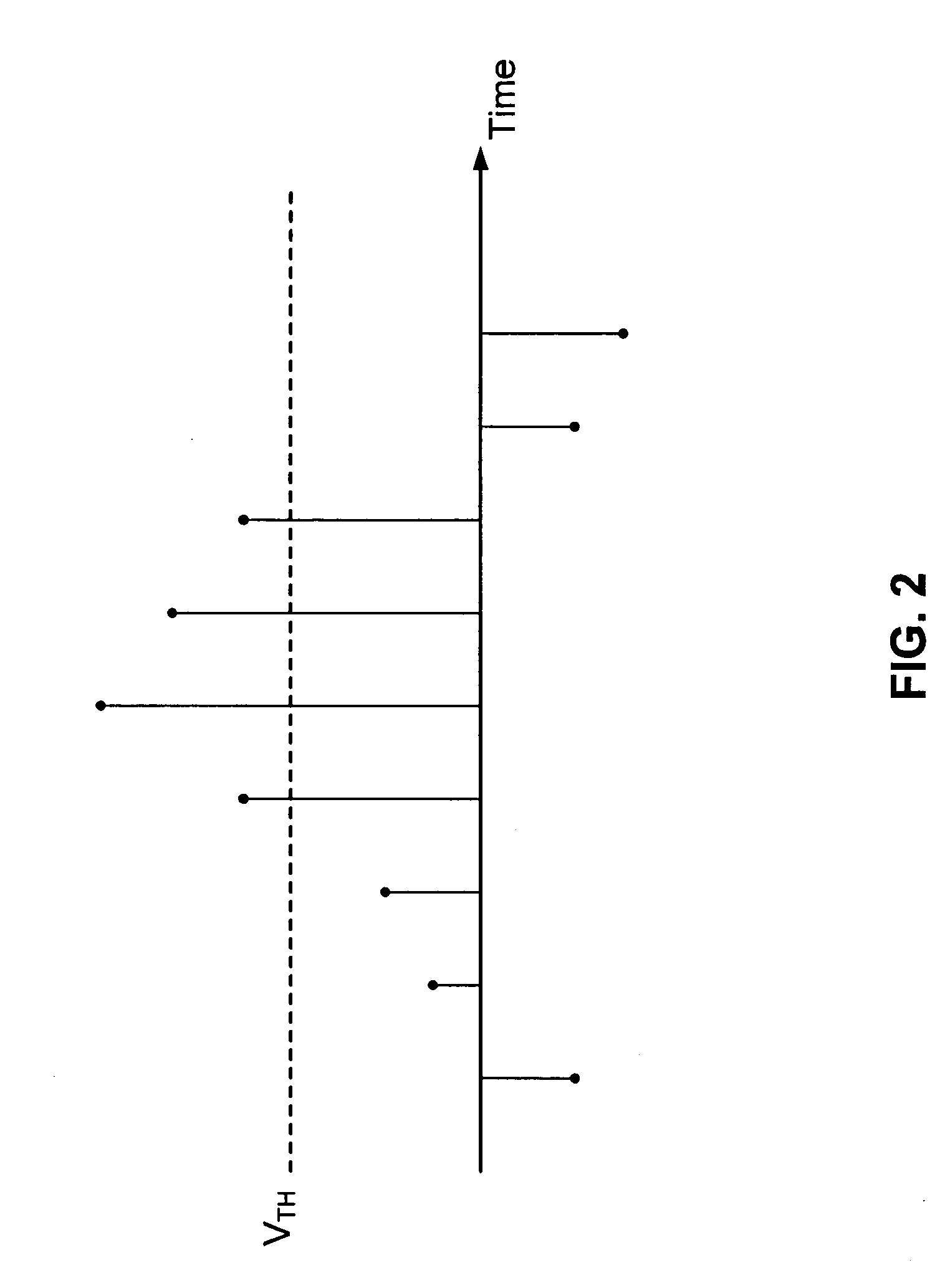
[0007]In one aspect the present invention provides a method of processing a band-limited, over-sampled signal comprising: reducing the amplitude of those portions of the signal having peaks above a threshold value; and controlling the frequency position of the noise associated with the reduction of such peaks. Thereby the crest factor of the signal is reduced. The amplitude of those portions of the signal having peaks above a threshold value are not limited to the threshold value. Whilst they may be reduced to a value at or below the threshold value, they may be reduced to a level which is above the threshold value.
[0015]In another aspect the present invention provides a method of processing a band-limited, over-sampled signal comprising: clipping the signal at a given threshold; subtracting the clipped signal from the signal; filtering the subtracted signal to thereby control the frequency position of the clipping noise; delaying the signal; and subtracting the filtered signal from the delayed signal, thereby reducing the amplitude of those portions of the signal housing peaks above the threshold.
[0020]The circuitry for controlling the frequency position of the noise may control the noise to be positioned outside the frequency band used by the signal. The circuitry for controlling the frequency position of the noise may control the noise to be positioned outside the frequency band used by a signal transmitted in the opposite direction. The signal may contribute an echo to the signal transmitted in the opposite direction.

Problems solved by technology

However, any such clipping generates broadband noise, usually on the whole bandwidth of the signal.
This noise causes loss of data: in the transmit direction by suddenly increasing the background noise; and in the receive direction due to the leakage of the noise through the hybrid.
Consequently, too frequent clipping causes degradation of the overall bit error ratio of the transmission, resulting in data being lost.
However, the use of a feedback loop makes the behaviour of the technique unpredictable when processing a sequence of pulses.
Whilst the technique works in a predictable fashion when processing two successive peaks, feeding the re-distributed noise of the first back to the second, with a sequence of peaks operation would be unstable.
With a sequence of peaks it would be difficult to predict the contribution made by successive peaks in the feedback loop, and the system would be too unpredictable for reliable operation.

Method used


Image

  • Power reduction
  • Power reduction
  • Power reduction

Examples


Embodiment Construction

[0025]The invention is described herein with reference to a particular example concerning the processing of a signal generated by an ADSL (asymmetric digital subscriber line) modem. Such a modem generates a DMT (discrete multi-tone) signal carrying multiple carrier frequencies. Such signals are band-limited, over-sample signals. However, the invention is not limited to the processing of such a signal, and may be more broadly applied to the processing of any band-limited, over-sampled signal. The invention is not limited in its applicability to multi-carrier signals, but may also apply to single carrier signals. The following description uses the example of a multi-carrier signal for illustrative purposes only.

[0026]As discussed in the introduction hereinabove, as a result of the combining of multiple carriers, the signal at the output of the modem contains random peaks which are above a desired threshold. The level of the desired threshold is user or implementation dependent.

[0027]R...


PUM


Abstract

There is disclosed a technique in which any peaks above a threshold level are reduced, but not clipped, such that the effects of such peaks is reduced. Although the implementation of the technique preferably includes a clipping step, it is performed on the front-end rather than as the last step in the technique, such that the output signal is not a clipped signal. Any noise introduced by the clipping step, so-called clipping noise, is preferably filtered out of the useful frequency band of the signal.

Description

FIELD OF THE INVENTION[0001]The present invention relates to a technique for reducing the maximal signal amplitude and hence the crest factor of a signal, for example, a multi-carrier signal such as a DMT (discrete multi-tone) signal, and particularly but not exclusively to such a signal generated by a modem.BACKGROUND OF THE INVENTION[0002]The amplitude distribution of a band-limited, over-sampled signal such as a multi-carrier signal, generated by an ADSL (asymmetric digital subscriber line) modem, can be considered as Gaussian with a zero mean and a variance equal to the power of the transmitter signal. The envelope of such multi-carrier signals randomly present, with a small probability, peaks of a very high amplitude. The span (i.e. the peak to peak voltage) of signals driven by the line driver, which is the component dedicated to transmit the power on the line, is important. The power consumption of the line driver is strongly related to the span of the voltage. In order to ke...

Claims


Application Information

Patent Timeline
Patent Type & Authority Patents(United States)
IPC IPC(8): H04L27/26
CPCH04L27/2624
Inventor PEETERS, MIGUEL PHILIPE PAUL
Owner AVAGO TECH INT SALES PTE LTD
Learn More