Extreme ultraviolet soft x-ray projection lithographic method system and lithographic elements

a technology of projection lithography and ultraviolet soft radiation, which is applied in the field of projection lithographic methods and systems, can solve the problems of adoption of extreme ultraviolet soft x-rays, affecting the commercial use of such radiation, and affecting the accuracy of lithographic elements

Inactive Publication Date: 2005-08-16
CORNING INC
View PDF47 Cites 22 Cited by
  • Summary
  • Abstract
  • Description
  • Claims
  • Application Information

AI Technical Summary

Benefits of technology

[0013]Additional features and advantage of the invention will be set forth in the detailed description which follows, and in part will be readily apparent to those skilled in the art from that description or recognized by practicing the invention as described herein, including the detailed description which follows, the claims, as well as the appended Figures.

Problems solved by technology

The use of extreme ultraviolet soft x-ray radiation provides benefits in terms of achieving smaller feature dimensions but due to the nature of the radiation, it presents difficulties in terms of manipulating and directing such wavelengths of radiation and has delayed the commercial manufacturing use of such radiation.
Current optical lithography systems used in the manufacturing of integrated circuits have progressed towards shorter optical wavelengths of light, such as from 248 nm to 193 nm to 157 nm, but the commercial use and adoption of extreme ultraviolet soft x-rays has been hindered.
Part of this slow progression to very short wavelengths of radiation such as in the 15 nm range, has been due to the lack of economically manufacturable mirror elements that can withstand the exposure to such radiation while maintaining a stable and high quality circuit pattern image.
As noted from U.S. Pat. No. 5,698,113, current extreme ultraviolet soft x-ray lithographic systems are extremely expensive.

Method used


Image

  • Extreme ultraviolet soft x-ray projection lithographic method system and lithographic elements
  • Extreme ultraviolet soft x-ray projection lithographic method system and lithographic elements
  • Extreme ultraviolet soft x-ray projection lithographic method system and lithographic elements

Examples


Embodiment Construction

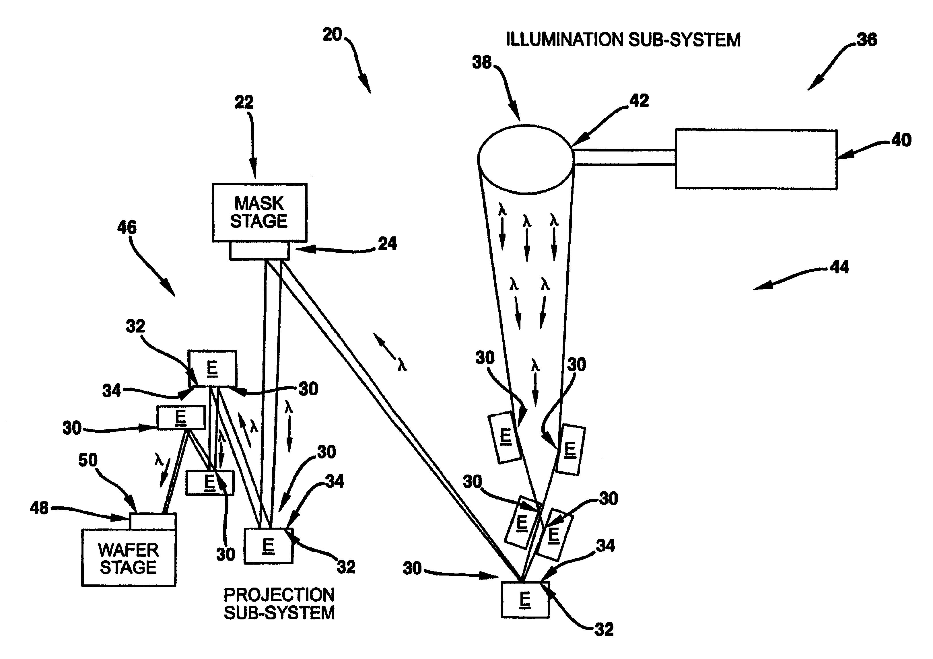
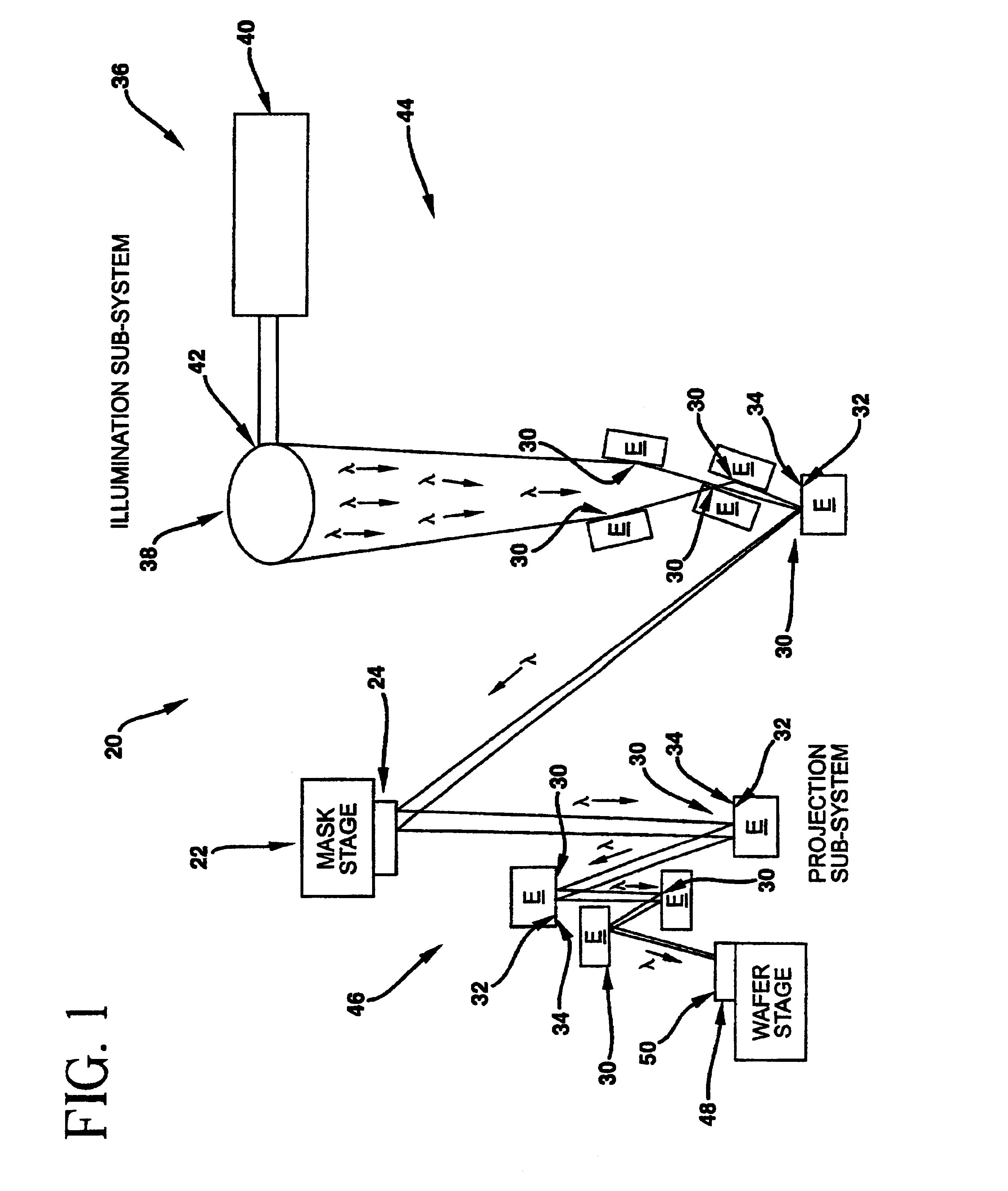
[0025]Reference will now be made in detail to the present preferred embodiments of the invention, examples of which are illustrated in the accompanying Figures. An exemplary embodiment of the projection lithographic method / system of the present invention is shown in FIG. 1 and is designated generally throughout by reference numeral 20.

[0026]In accordance with the invention, the present invention for a projection lithographic method includes providing a mask stage illuminated by extreme ultraviolet soft x-ray radiation λ produced by an illumination sub-system, with the mask stage including a mask for forming a projected mask pattern when illuminated by radiation λ. The invention includes providing Ti doped high purity SiO2 glass lithography elements which manipulate radiation λ and operate on the projected mask pattern.

[0027]As embodied herein, and depicted in FIG. 1, projection lithographic method / system 20 comprises mask stage 22 which includes circuit patterned reflective mask 24....


PUM

PropertyMeasurementUnit
operating temperatureaaaaaaaaaa
spatial frequency roughnessaaaaaaaaaa

Abstract

The projection lithographic method for producing integrated circuits and forming patterns with extremely small feature dimensions includes an illumination sub-system (36) for producing and directing an extreme ultraviolet soft x-ray radiation λ from an extreme ultraviolet soft x-ray source (38); a mask stage (22) illuminated by the extreme ultraviolet soft x-ray radiation λ produced by illumination stage and the mask stage (22) includes a pattern when illuminated by radiation λ. A protection sub-system includes reflective multilayer coated Ti doped high purity SiO2 glass defect free surface (32) and printed media subject wafer which has a radiation sensitive surface.

Description

CROSS-REFERENCE TO RELATED PATENT APPLICATIONS[0001]This application claims the benefit of U.S. Provisional Application Ser. No. 60 / 145,057, filed Jul. 22, 1999 entitled Extreme Ultraviolet Soft X-Ray Projection Lithographic Method and Mask Devices of Claude L. Davis, Robert Sabia and Harrie J. Stevens, and U.S. Provisional Application Ser. No 60 / 149,840, filed Aug. 19, 1999 entitled Extreme Ultraviolet Soft X-Ray Projection Lithographic Method and Mask Devices of Claude L. Davis, Robert Sabia, Harrie J. Stevens and Kenneth E. Hrdina, and U.S. Provisional Application Ser. No. 60 / 158,813, filed Oct. 12, 1999 entitled Extreme Ultraviolet Soft X-Ray Projection Lithographic Method and Mask Devices of Claude L. Davis and Kenneth E. Hrdina.BACKGROUND OF THE INVENTION[0002]1. Field of the Invention[0003]The present invention relates generally to projection lithographic methods and systems for producing integrated circuits and forming patterns with extremely small feature dimensions. The pr...

Claims


Application Information

Patent Timeline
Patent Type & Authority Patents(United States)
IPC IPC(8): G03F7/20C03B8/04C03B20/00C03C17/36G02B5/08G02B5/10G02B5/26G02B5/28G02B17/06G03F1/00G03F1/24G03F1/60G21K1/06G21K5/02H01L21/027
CPCB82Y10/00B82Y40/00G02B5/0891G02B17/0615G02B17/0636G03F1/14G03F1/24G03F1/60G03F7/702G03F7/70233G03F7/70283G03F7/70891G03F7/70958G21K1/062C03B19/1415G21K2201/064G21K2201/067C03B2201/07C03B2201/42
Inventor DAVIS, JR., CLAUDE L.HRDINA, KENNETH E.
Owner CORNING INC
Why Eureka
Try Eureka