Frequency dependent excursion limiter

a limiter and frequency-dependent technology, applied in the direction of transducer casing/cabinet/support, electric transducers, tone control, etc., can solve the problem of reducing the potential for unintendent driving of op amps beyond their rated range, and reduce the number of circuit elements. , the effect of reducing the potential for unintendent driving

Active Publication Date: 2005-08-16
MEYER SOUND LABORATORIES
View PDF9 Cites 58 Cited by
  • Summary
  • Abstract
  • Description
  • Claims
  • Application Information

AI Technical Summary

Benefits of technology

[0010]Briefly, the invention is an improved frequency-dependent excursion limiter circuit for protecting the transducers of a loudspeaker system or other system from mechanical overload. The circuit includes an first summing stage for receiving an input signal, a clamping stage following the summing stage for providing a voltage clamping function which limits the voltage of the input signal passed through the clamping stage to a predetermined maximum voltage which is substantially independent of frequency. A shaping filter stage follows the clamping stage and provides a frequency response shaping function based on predetermined frequency response shaping criteria derived from the determined excursion limits of the loudspeaker over a range of frequencies. In accordance with the invention, the shaping filter stage has at least one local feed forward branch filter, the output of which is summed with the output from the cl...

Problems solved by technology

Furthermore, eliminating op amp based circuits before clamping reduce...

Method used


Image

  • Frequency dependent excursion limiter
  • Frequency dependent excursion limiter
  • Frequency dependent excursion limiter

Examples


Embodiment Construction

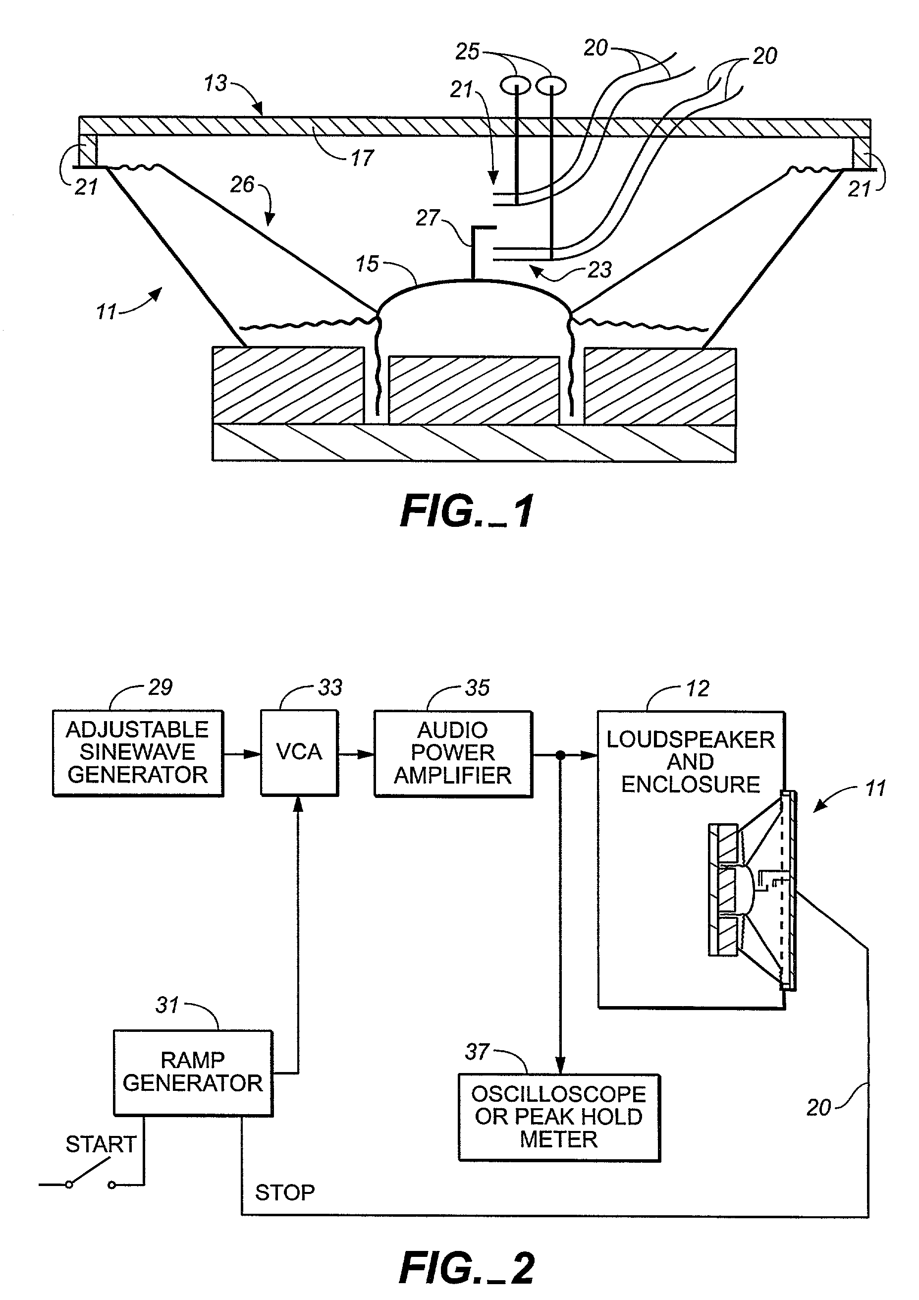
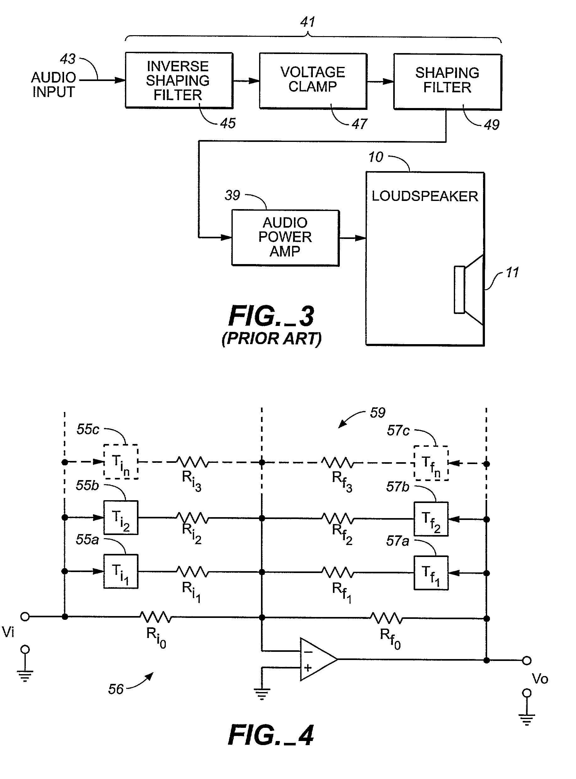
[0030]Referring now to the drawings, FIGS. 1 and 2 illustrate a technique for measuring the maximum safe peak voltage of a loudspeaker transducer within its enclosure in order to develop criteria for designing suitable filters for the improved frequency-dependent excursion limiting circuit of the invention. Such measurement techniques have been practiced in connection with the prior art circuit of FIG. 3 described herein.

[0031]In FIG. 1, the transducer of a loudspeaker is shown in the form of a cone driver 11. Also shown is an excursion detector 13 mounted to the front of the cone driver to measure the excursion of the driver's dust cap 15. The excursion detector is comprised of a bridge member 17, suitably be manufactured of a ¼ inch square metal bar, mounted to the rim 19 of the cone driver by means of stand-off posts 21. Bridge member 17 carries two low force contact switches 22, 23 having suitable depth adjustments 25 to adjust the position of the contact switches to a position ...


PUM


Abstract

A circuit and method provides for the protection of transducers from over excursion, particularly for the protection of transducers for audio loudspeakers. A frequency dependent excursion limiter circuit has an initial summing stage followed by a shaping filter stage. A clamping function is provided at the summing stage, or at a separate stage between the summing stage and the shaping filter stage, for clamping the driving signal at a predetermined maximum voltage if the driving signal exceeds the predetermined maximum voltage level. The shaping filter stage provides a frequency response shaping function based on a predetermined frequency response shaping criteria which is related to the frequency dependent excursion limits of the transducers being protected from mechanical overload. An inverse shaping filter function is provided at the initial summing stage by providing feedback from the shaping filter stage, thus eliminating the need for a separate inverse shaping filter circuit before clamping. The inverse shaping filter function allows low level signals below clamping to pass through the circuit unaffected.
A frequency dependent excursion limiter circuit is also provided in the closed loop circuit of servo feedback system for protecting transducers in a servo feedback system from over excursion.

Description

CROSS REFERENCE TO RELATED APPLICATIONS[0001]Applicant claims the benefit of provisional application Ser. No. 60 / 239,013, filed Oct. 6, 2000.BACKGROUND OF THE INVENTION[0002]The present invention generally relates to the protection of transducers from over excursion, and more particularly relates to circuits and methods for protecting the transducers of audio loudspeakers when used conventionally and within a closed loop system.[0003]The potential for overdriving loudspeakers is a problem that must be taken into account in the design of sound reinforcement systems. Overdriving a loudspeaker can cause damage to the transducers of the loudspeaker system, resulting in degradation or total failure in the performance of the loudspeaker and costly repairs. This problem is made acute by the fact that modern audio power amplifiers are capable of producing output power levels that far exceed the capacity of the loudspeakers to which they are connected. Amplifier output power ratings greater ...

Claims


Application Information

Patent Timeline
IPC IPC(8): H03G11/00H03G11/02H04R3/00
CPCH03G11/00H03G11/02H04R3/007
Inventor KOHUT, PAUL
Owner MEYER SOUND LABORATORIES
Why Eureka
Try Eureka