Coupling a tapered optical element to an optical fiber

a tapered optical element and optical fiber technology, applied in the field of coupling, can solve the problems of unsuitable methods for coupling tapered optical elements, and achieve the effect of reducing the loss of fresnel reflection

Inactive Publication Date: 2005-08-16
HONEYWELL INT INC
View PDF11 Cites 26 Cited by
  • Summary
  • Abstract
  • Description
  • Claims
  • Application Information

AI Technical Summary

Benefits of technology

[0005]The present invention describes an apparatus and method of using a coupler to couple a tapered optical element to an optical fiber. In a preferred embodiment, the inventive coupler comprises a hollow silicone insert in a metal tube that is used to align an optical fiber and a tapered non-imaging optical element. A crimp tool deforms the metal tube and the coupler enough to fix the fiber and non-imaging optic in alignment. The silicone insert enables direct contact with the non-imaging optic without loss of total internal reflection. In accordance with my invention, the silicone insert includes “grabber features” to clamp around the parts. Advantageously, an index-matching medium is in contact with the opposing faces of the parts, reducing the fresnel reflection loss from 8% to less than 1%.

Problems solved by technology

While there are methods known for coupling fiber optic cables to one another, such methods have proven to be unsuitable for coupling a tapered optical element, such as a morphing concentrator, to an optical fiber.

Method used


Image

  • Coupling a tapered optical element to an optical fiber
  • Coupling a tapered optical element to an optical fiber
  • Coupling a tapered optical element to an optical fiber

Examples


Embodiment Construction

Mode(s) for Carrying Out the Invention

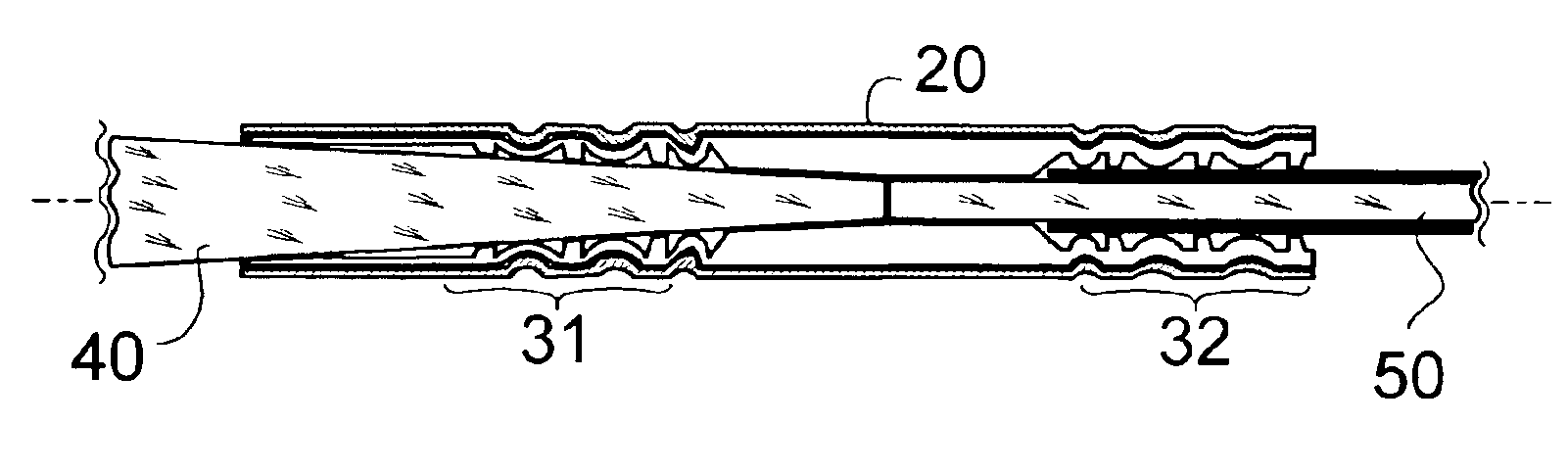
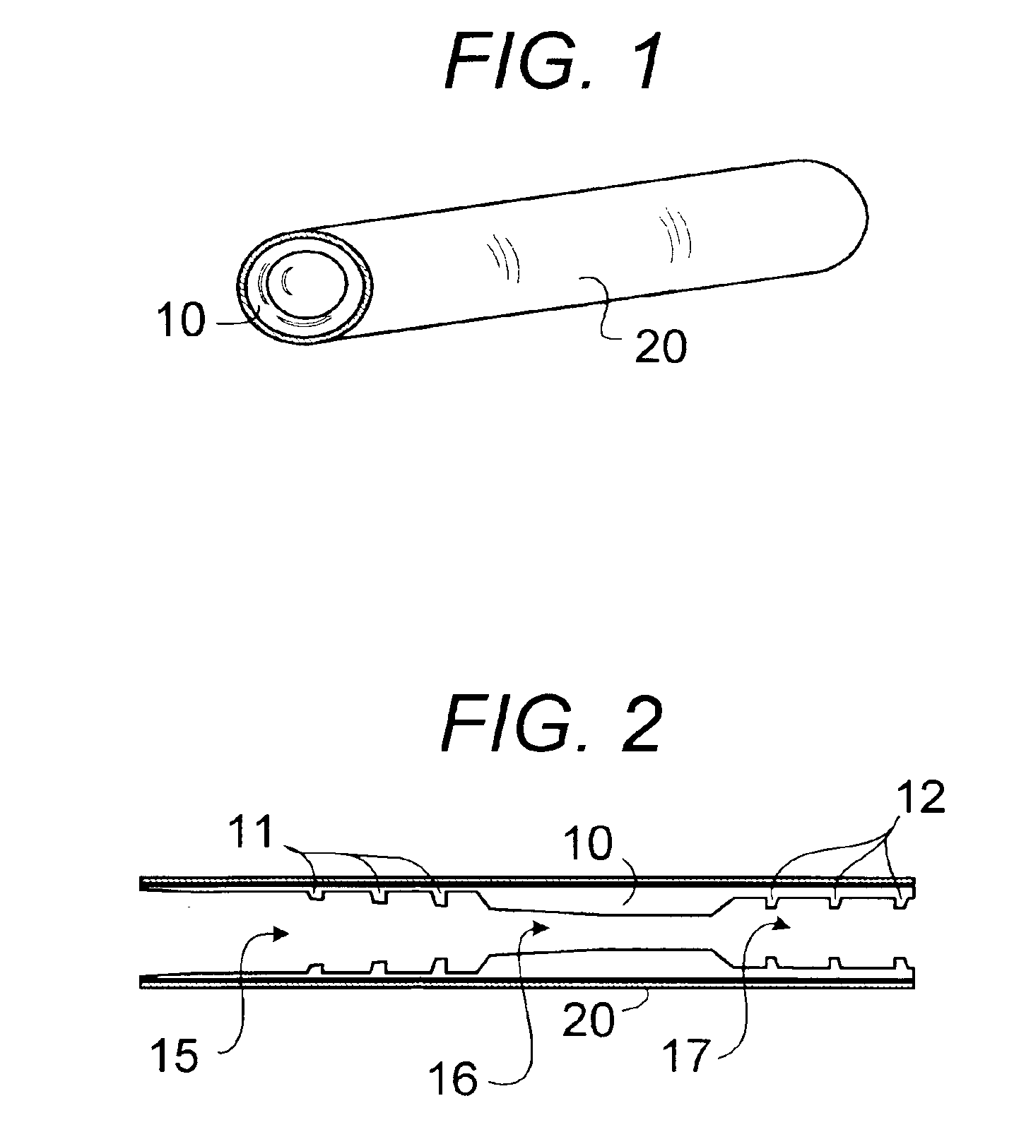
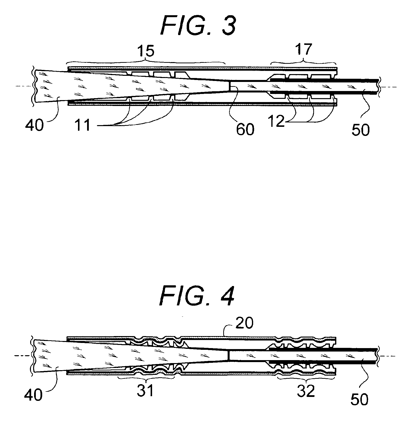
[0028]Referring first to FIG. 1, a fiber optic coupler in accordance with one embodiment of my invention comprises a clear hollow insert 10, composed of a material such as silicone, within a deformable tube 20. The material used for the clear hollow insert advantageously has a lower refractive index than the tapered optical element or a coating of a lower refractive index is provided between the hollow insert 10 and the tapered optical element to prevent light leakage. In one particular embodiment, tube 20 is of metal and has an outer diameter of 5.7 millimeters and an inner diameter of 5.2 millimeters.

[0029]FIG. 2 shows the internal structure of the fiber optic coupler of FIG. 1, before its use as a coupling element. The clear hollow insert 10 is composed of an input tapered region 15, a coupling region 16, and a constant area region 17 and advantageously is a molded part positioned against the inner surface of the metal tube 20. The input tape...


PUM

PropertyMeasurementUnit
inner diameteraaaaaaaaaa
refractive indexaaaaaaaaaa

Abstract

A fiber optic coupler comprises a metal tube and a clear hollow silicone insert, with a tapered region including a first set of grabbers and a constant area region including a second set of grabbers. A tapered optical element is coupled to an optical fiber, when both the tapered optical element and the optical fiber are mechanically secured by crimping the metal tube and the silicone insert in the proximity of the first and second sets of grabbers, as by using a standard crimper tool.

Description

BACKGROUND OF THE INVENTION[0001]1. Technical Field[0002]This invention relates to the field of fiber optic illumination and more specifically to a coupler suitable for attaching a tapered optical element to an optical fiber.[0003]2. Background Art[0004]While there are methods known for coupling fiber optic cables to one another, such methods have proven to be unsuitable for coupling a tapered optical element, such as a morphing concentrator, to an optical fiber. There is therefore a need to be able to cost effectively couple an optical fiber to a tapered non-imaging optical element especially for non-imaging optics applications.SUMMARY OF THE INVENTION[0005]The present invention describes an apparatus and method of using a coupler to couple a tapered optical element to an optical fiber. In a preferred embodiment, the inventive coupler comprises a hollow silicone insert in a metal tube that is used to align an optical fiber and a tapered non-imaging optical element. A crimp tool def...

Claims


Application Information

Patent Timeline
Patent Type & Authority Patents(United States)
IPC IPC(8): G02B6/36G02B6/26G02B6/24G02B6/32G02B6/38G02B27/09
CPCG02B6/241G02B6/262G02B6/32G02B6/3624G02B27/0994G02B6/3806G02B6/3857G02B6/382
Inventor SACCOMANNO, ROBERT J.
Owner HONEYWELL INT INC
Why Eureka
Try Eureka