Method for determining the pressure present in the interior space of an air spring for a motor vehicle and apparatus for carrying out the method

a technology of air spring and interior space, which is applied in the direction of fluid pressure measurement by acoustic means, counting objects on conveyors, and cathode ray tubes/electron beam tubes, etc., can solve the problems of relatively high technical complexity, control units, and the pressure measurement method is not particularly sensitive and therefore is rather imprecise, and achieves cost-effective effects

Inactive Publication Date: 2005-08-23
VAHRENWALDER STRASSE 9
View PDF4 Cites 23 Cited by
  • Summary
  • Abstract
  • Description
  • Claims
  • Application Information

AI Technical Summary

Benefits of technology

[0004]It is an object of the invention to provide a cost-effective and precisely functioning method for measuring the static pressure in an air spring wherein the measured air pressure in the air spring can be used also for pressure corrections in a distance measuring method known per se.
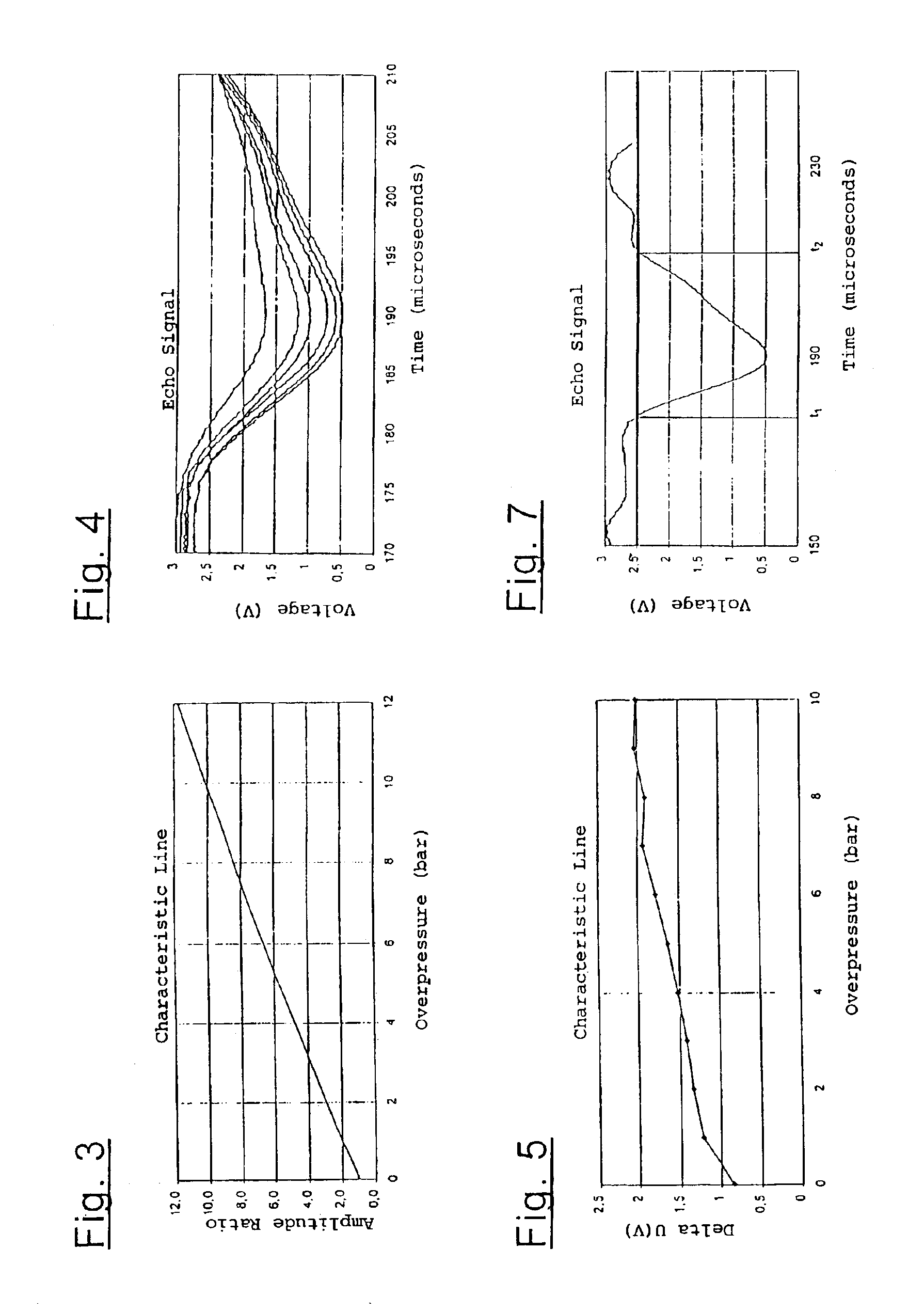
[0019]The relationship between pressure and the amplitude ratio is in the present method significantly greater than in the method of U.S. Pat. No. 6,073,491. In this way, the complexity is reduced in the evaluation.

Problems solved by technology

From theoretical considerations, it results that this pressure-measurement method is not especially sensitive and therefore is rather imprecise.
A further disadvantage is the relatively high technical complexity, namely, two reference reflectors and a control unit for the transmitting power are necessary.

Method used


Image

  • Method for determining the pressure present in the interior space of an air spring for a motor vehicle and apparatus for carrying out the method
  • Method for determining the pressure present in the interior space of an air spring for a motor vehicle and apparatus for carrying out the method
  • Method for determining the pressure present in the interior space of an air spring for a motor vehicle and apparatus for carrying out the method

Examples


Embodiment Construction

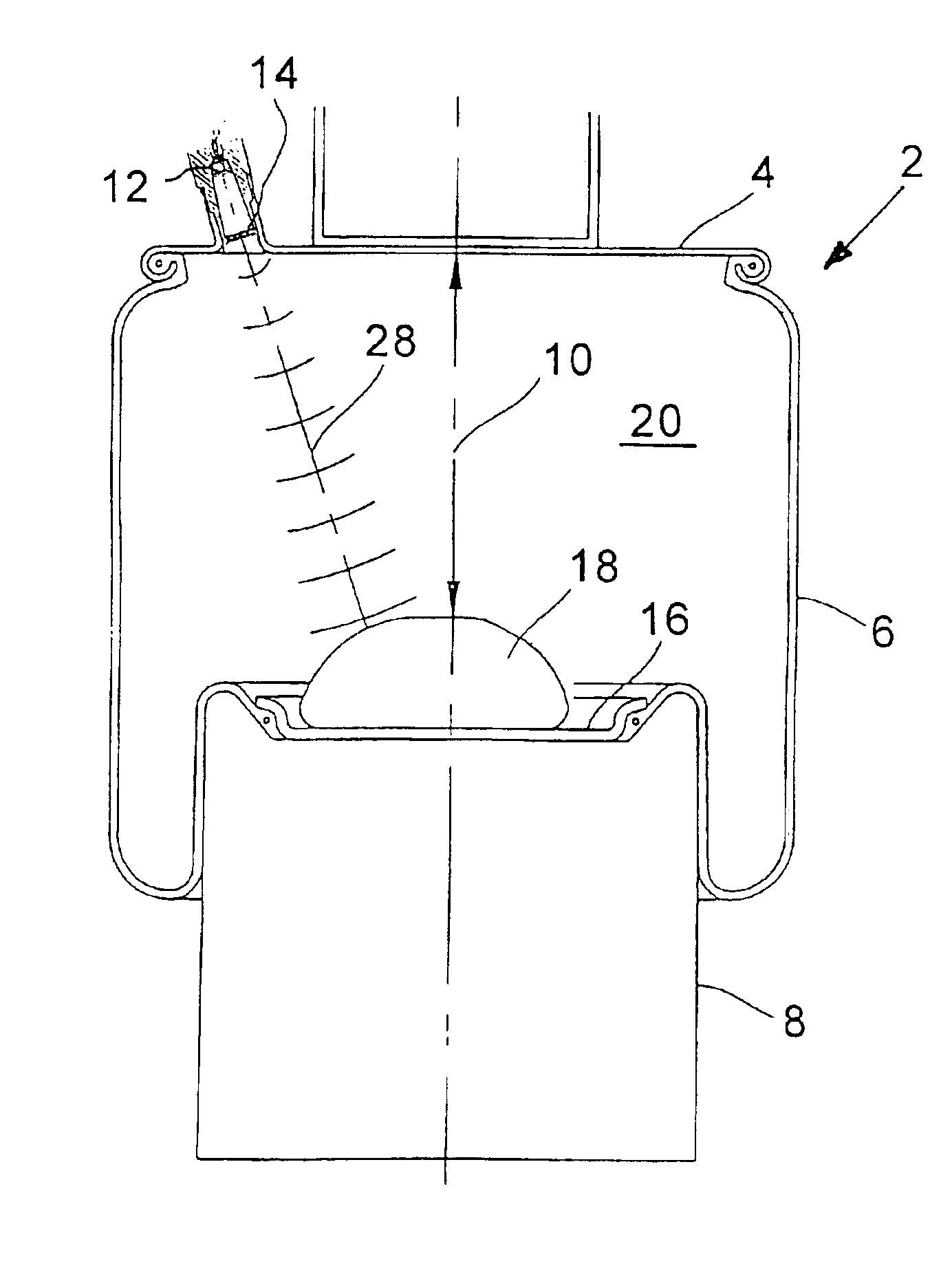
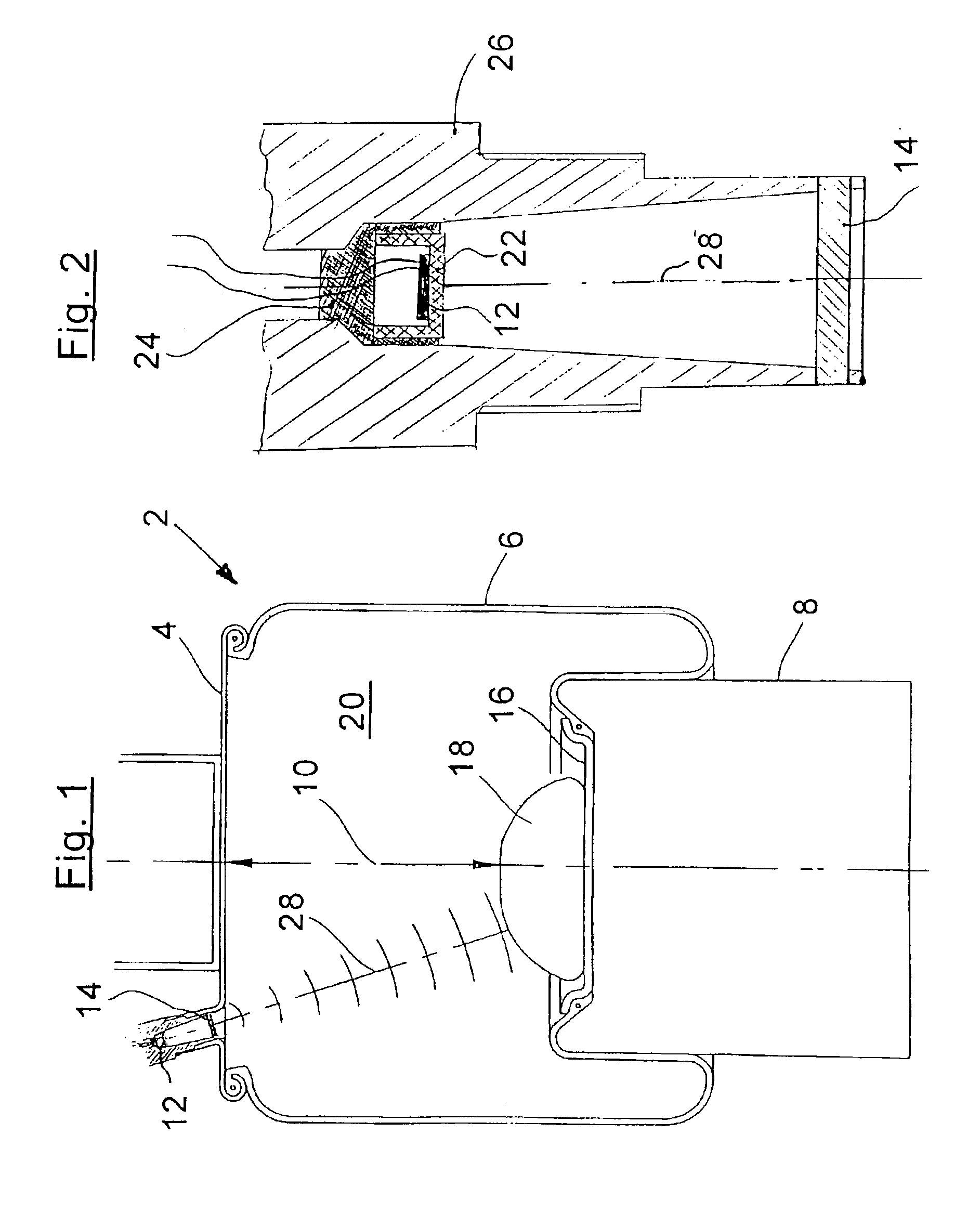
[0030]The air spring 2 shown in FIG. 1 includes essentially a cover plate 4, a flexible member 6 and a roll-off piston 8. The cover plate 4 is mounted on the chassis and the roll-off piston 8 is mounted at the axle end or wheel end. During the deflection operation, the flexible member 6 rolls on the roll-off piston 8. The clear distance 10 between the clamp plate 16 of the roll-off piston 8 or a bumper 18 and the cover plate 4 is dependent upon the deflection and loading state of the vehicle.

[0031]For measuring this distance 10, a piezoceramic ultrasonic transducer 12 is disposed on the cover plate 4 and is configured as a transmitter and receiver.

[0032]A reference reflector is mounted at a fixed distance ahead of the ultrasonic transducer 12. The reference reflector 14 can be simply a tensioned wire. The ultrasonic transducer 12 is directed in the direction toward the roll-off piston 8 or, when utilizing a clamp plate 16, the ultrasonic transducer is directed toward the latter. In ...


PUM

PropertyMeasurementUnit
pressureaaaaaaaaaa
pressureaaaaaaaaaa
pressureaaaaaaaaaa

Abstract

An ultrasonic pulse / echo measurement arrangement includes an ultrasonic transducer (12), which is mounted spatially fixed on an air spring cover plate (4). The arrangement further includes a fixedly mounted reference reflector (14), a target reflector (16) mounted on a roll-off piston (8) or on the bumper (18) as well as a transmitter / receiver evaluation electronic circuit (30). The running time as well as the amplitude of the reference signal is evaluated to precisely determine the pressure present in the interior space of the air spring. The ultrasonic transducer (12) has a λ / 4-adaptation layer (22), whose impedance does not correspond to the geometric mean of the impedances of the ultrasonic transducer (12) and the ambient air of the interior space (20) of the air spring, but rather, is a mismatch. The evaluation electronic circuit (30) can be calibrated at ambient pressure for the determination of the inner pressure of the air spring. Preferably, the pressure measuring method according to the invention is also used to determine the running-time dependent spring height in an air spring (2) of a motor vehicle.

Description

FIELD OF THE INVENTION[0001]The invention relates to an ultrasonic method for measuring pressure in an air spring and the use of the measuring result to make corrections in a distance measuring method. Furthermore, the invention relates to an arrangement for carrying out the method. The arrangement includes a piezoceramic ultrasonic transducer, a reflector, a reference reflector and an electronic circuit.BACKGROUND OF THE INVENTION[0002]U.S. Pat. No. 6,073,491 discloses an arrangement and a method for the contactless distance and pressure measurement within an air spring. Both measurement quantities are determined in accordance with the pulse / echo method with the aid of ultrasonic pulses, which propagate within the air spring flexible member. The distance between the ultrasonic transducer and an end reflector is computed from the running times of the sonic pulses to a first reference reflector and to the end reflector. The static pressure present in the air spring is determined with...

Claims


Application Information

Patent Timeline
Patent Type & Authority Patents(United States)
IPC IPC(8): B60G17/015B60G17/019F16F9/05F16F9/02G01L11/06G01L11/00G01S15/02G01S15/88G01S15/00G01S7/521B60G17/00
CPCB60G17/01933F16F9/05F16F9/052G01L11/06G01S7/521G01S15/025G01S15/88B60G2204/111B60G2400/252B60G2401/176F16F2230/08G01N2291/02872G01S2007/52014G01S15/86
Inventor RECK, SIEGFRIED
Owner VAHRENWALDER STRASSE 9
Why Eureka
Try Eureka