
Measuring pressure exerted by a rigid surface

a technology of rigid surfaces and pressure, applied in the direction of force measurement, instruments, measurement devices, etc., can solve the problems of large load cells, inconvenient use, and inability to measure the pressure distribution across the body with millimeter resolution, so as to achieve accurate pressure measurement and high special resolution

Inactive Publication Date: 2005-08-23
KNIRCK JEFFREY G +1
View PDF13 Cites 33 Cited by
  • Summary
  • Abstract
  • Description
  • Claims
  • Application Information

AI Technical Summary

Benefits of technology

[0013]In accordance with the above, this invention provides a means to accurately measure a pressure or a pressure distribution across a rigid or semi-rigid surface with high special resolution.
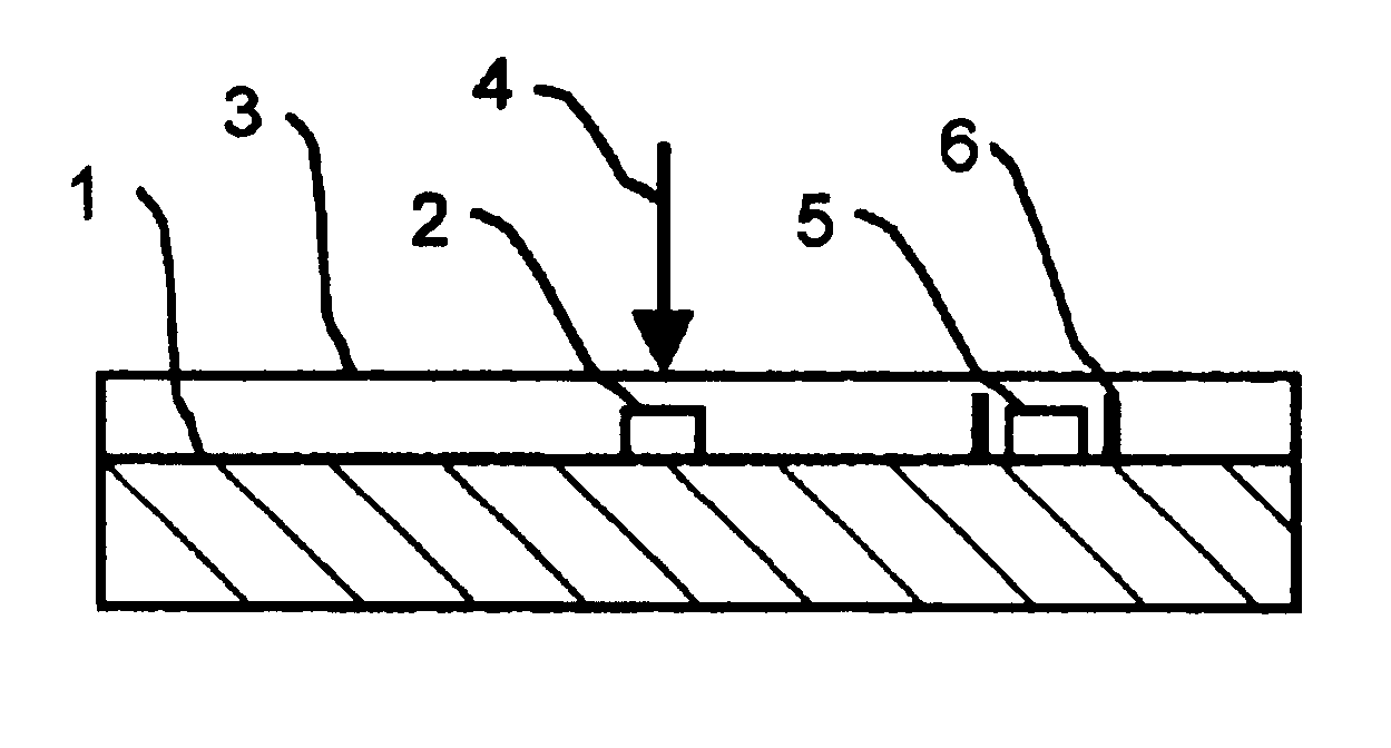
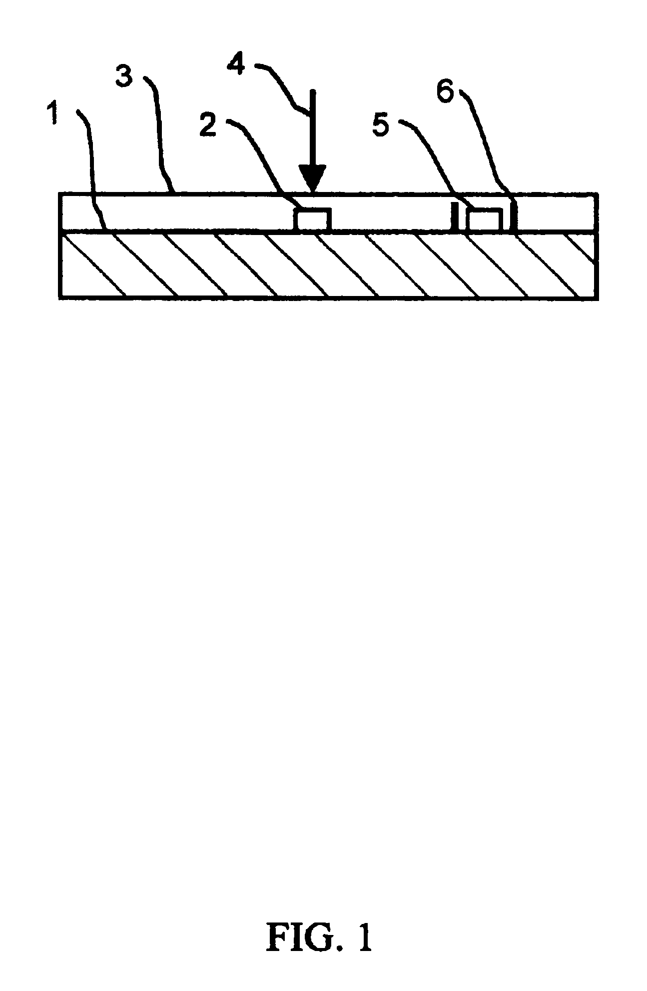
[0014]The present invention accomplishes its objective by using one or more commercial micro-machined silicon pressure sensor die. The dies are then covered with a thin layer of elastomeric material. The use of commercial pressure sensor die provides a precise and accurate measurement and they are very small. The elastomer layer provides a slightly deformable layer over the rigid sensor die. When the sensor array assembly of this invention comes in contact with a rigid body the elastomer is compressed which in turn applies a force on the silicon diaphragm incorporated in the sensor die, thereby producing an electrical signal. This feature of the present invention allows it to be used to measure a wide range of material surface types from fluids to very rigid solids, and everything in between.

Problems solved by technology

Load-cells are typically large and not well suited to being used in an array to sense the uniformity of force between two bodies.
Measuring the pressure distribution across a body with millimeter resolution could not be done with commercial load-cells.
Other gap-sensing approaches can be far more precise and accurate but they are also far more costly.
There are a few important problems with the basic scheme.
Typically there are performance problems associated with sensitivity, linearity, accuracy, hysterisis, aging, and temperature effects.

Method used


Image

  • Measuring pressure exerted by a rigid surface
  • Measuring pressure exerted by a rigid surface

Examples


Embodiment Construction

[0017]The present invention provides a means to precisely, simultaneously and accurately measure the pressure distribution produced by a rigid or semi-rigid surface, or between two rigid or semi-rigid surfaces. A semi-rigid body may be soft, pliable, flexible or elastomeric, but it is differentiated from a gas or a liquid since such fluids perfectly conform to their container and won't support a static pressure gradient. The present invention is a pressure sensor apparatus. A multiple pressure sensor apparatus could be arranged in an array or other grouping or collection. The Pressure Sensor is comprised of a commercial silicon micro-machined pressure sensor die embedded in an elastomer. An array may be constructed from individual micro-machined die or multiple pressure sensors in a monolithic micro-machined block. The advantages of the present invention are its precision, accuracy, stability and high spatial resolution.

[0018]The details of the present invention can be implemented i...


PUM


Abstract

A means to accurately measure the pressure distribution across a rigid or semi-rigid surface, or between two rigid or semi-rigid surfaces with high special resolution is disclosed. The present invention relates to measuring a pressure distribution. The present invention would be ideal for use in various types of manufacturing tooling and various in situ industrial machine controls. The present invention uses an array of commercial micro-machined silicon pressure sensing die attached to a substrate and encapsulated in an elastomer.

Description

CROSS-REFERENCE TO RELATED APPLICATIONS[0001]Not ApplicableSTATEMENT REGARDING FEDERALLY SPONSORED RESEARCH OR DEVELOPMENT[0002]Not ApplicableBACKGROUND OF THE INVENTION[0003]The present invention relates to sensing the pressure or pressure distribution created between two rigid surfaces.[0004]Pressure sensing devices are typically optimized for sensing the pressure of a fluid like a liquid or a gas. In such a case a single measurement will typically suffice because there is no pressure gradient. When two rigid bodies exert a load on each other a Load-cell is traditionally used. A load-cell measures the total force between the two bodies. Load-cells are typically large and not well suited to being used in an array to sense the uniformity of force between two bodies. Small load-cells are approximately one cubic centimeter. Measuring the pressure distribution across a body with millimeter resolution could not be done with commercial load-cells.[0005]Thin, flexible pressure sensitive s...

Claims


Application Information

Patent Timeline
IPC IPC(8): G01L9/00G01L1/20
CPCG01L1/205G01L9/0002
Inventor KNIRCK, JEFFREY G.SWANSON, PAUL A.
Owner KNIRCK JEFFREY G
Learn More