Apparatus and method for direct analysis of formation composition by magnetic resonance wireline logging

a technology of magnetic resonance wireline logging and apparatus, applied in the field of geological exploration, can solve the problem that the methodology does not directly detect the signals continuously emitted by moving magnetized materials, and achieve the effect of high special resolution

Active Publication Date: 2020-02-13
WOLLIN VENTURES
View PDF1 Cites 1 Cited by
  • Summary
  • Abstract
  • Description
  • Claims
  • Application Information

AI Technical Summary

Benefits of technology

[0008]This disclosure provides for, among other things, a device including a permanent magnet and coils that can identify producible hydrocarbons with high special resolution. This disclosure also provides for, among other things, a method for directly determining productive levels during hydrocarbon wire line well logging. The method may include direct detection of a continuous signal from carbon 13 as a surrogate for hydrocarbon, enabled by continuous phase modulated dual resonance excitation of both hydrogen protons and carbon 13 atoms in a formation deep to borehole effects, and may involve electronic and circuitry modification of wire line logging tools. Logging speed can be adjusted to discriminate against non-producible surface-associated hydrocarbon, solid hydrocarbon, bitumin, and viscous high density hydrocarbon as those compounds have short T2 spin spin dephasing. Thus, signals received from carbon 13 atoms would be from producible hydrocarbon.
[0009]Analysis of the motion of an isolated spin, as described more completely below, yields an elliptic integral of the first kind which is not integrable in closed form. However, look-up tables may be used to provide the value of the integral for each value of the colatitude (flip angle) and each value of the periodic phase angle. The continuous reception of a signal with a known periodic phase angle phase modulates the emitted signal and provides the continuously detected continuously emitted signal with an extremely narrow bandwidth, markedly limiting Johnson-Nyquist noise, at known sideband frequencies displaced from the applied B1 radio frequency field permitting continuous detection of the emitted signal in the presence of the applied constant frequency B1 field by cross-correlation with those known frequencies.

Problems solved by technology

This methodology does not directly detect signals continuously emitted by the moving magnetized material.

Method used


Image

  • Apparatus and method for direct analysis of formation composition by magnetic resonance wireline logging
  • Apparatus and method for direct analysis of formation composition by magnetic resonance wireline logging

Examples


Embodiment Construction

[0020]The following description is directed to certain implementations for the purposes of describing the innovative aspects of this disclosure. However, a person having ordinary skill in the art will readily recognize that the teachings herein can be applied in a multitude of different ways. The described implementations may be implemented in any device, apparatus, or system that is capable of measuring nuclide composition of magnetized material.

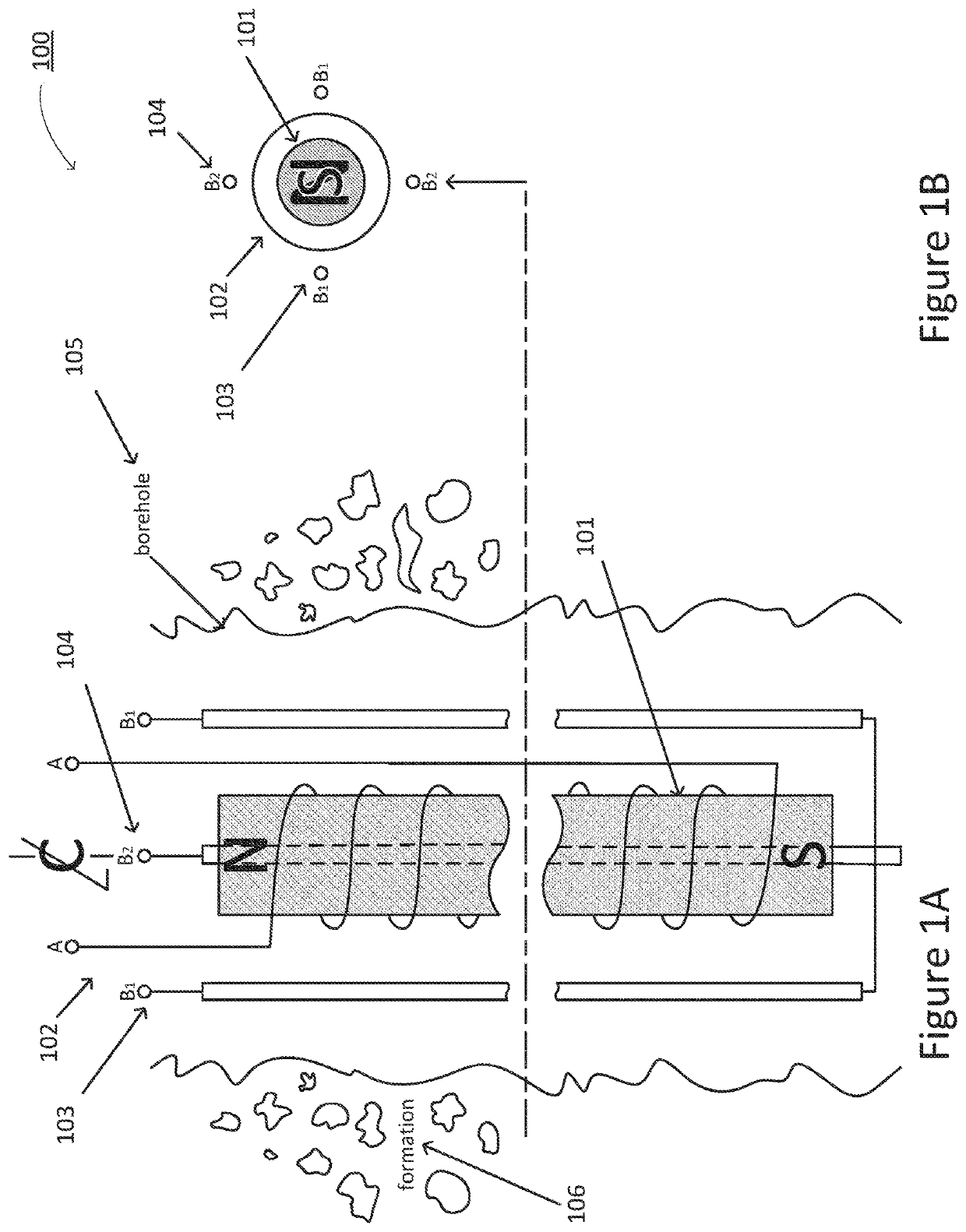
[0021]The following disclosure pertains to measuring nuclide composition of material within a borehole or peripherally in a surrounding formation. The borehole may be present in an earth formation or a man-made structure. The borehole may contain a logging tool employing nuclear spin or electron spin magnetic resonance for measurement. Applications of the logging tool disclosed herein include, without limitation, hydrocarbon production, hydraulic fracturing, groundwater migration, contaminant diffusion, or detecting formation migration or t...


PUM

PropertyMeasurementUnit
magnetic fieldaaaaaaaaaa
frequencyaaaaaaaaaa
Larmor frequencyaaaaaaaaaa

Abstract

A wireline or logging while drilling device includes: a first coil configured to vary the intensity of a main magnetic field so as to produce phase modulation of signals emitted by spins in a sensitive volume; and a second coil configured to excite the spins in the sensitive volume in an inverse ratio of gyromagnetic constants of the spins; and receive signals from the spins displaced in frequency from the Larmor frequency of the spins by the phase modulation produced by the first coil.

Description

CROSS REFERENCE TO RELATED APPLICATIONS[0001]This application is a continuation-in-part of application Ser. No. 14 / 874,835, filed Oct. 5, 2015, entitled “APPARATUS AND METHOD FOR MEASURING VELOCITY AND COMPOSITION OF MATERIAL IN AND ADJACENT TO A BOREHOLE,” which claims priority to Provisional Application No. 62 / 060,321, filed Oct. 6, 2014, entitled “APPARATUS AND METHOD FOR MEASURING VELOCITY AND COMPOSITION OF MATERIAL IN AND ADJACENT TO A BOREHOLE,” the disclosures of all of which are incorporated by reference herein in their entirety. Furthermore, this application claims priority to Provisional Application No. 62 / 733,383, filed Sep. 19, 2018, entitled “APPARATUS AND METHOD FOR DIRECT ANALYSIS OF FORMATION COMPOSITION BY MAGNETIC RESONANCE WIRELINE LOGGING,” the disclosure of which is incorporated by reference herein in its entirety.BACKGROUND OF THE INVENTION[0002]This disclosure relates to the field of geological exploration, and in particular to apparatus and methods for conti...

Claims


Application Information

Patent Timeline
Patent Type & Authority Applications(United States)
IPC IPC(8): G01V3/32G01F1/716
CPCG01V3/32G01F1/716G01N24/081G01R33/3808G01R33/381G01R33/383G01R33/445
Inventor WOLLIN, ERNEST
Owner WOLLIN VENTURES
Why Eureka
Try Eureka