Leadscrew mechanical drive with differential leadscrew follower structure

a technology of follower structure and lead screw, which is applied in the direction of mechanical equipment, gearing, hoisting equipment, etc., can solve the problems of limited ability to achieve the desired slow linear movement, physical limitations, and limited rotational output speed of the motor, and achieve the effect of small linear movement ra

Inactive Publication Date: 2005-08-23
RAYTHEON CANADA LTD
View PDF7 Cites 10 Cited by
  • Summary
  • Abstract
  • Description
  • Claims
  • Application Information

AI Technical Summary

Benefits of technology

[0010]In a conventional leadscrew mechanical drive where the thread pitch of the leadscrew and the thread pitch of the leadscrew follower structure are the same, the leadscrew follower structure engages the leadscrew over several turns and moves linearly by the amount of the thread pitch with each revolution of the leadscrew. In the present approach where the thread pitches of the leadscrew and the leadscrew follower structure are different, the leadscrew follower structure moves linearly by the difference between the thread pitches with each revolution of the leadscrew, thereby achieving a differential drive effect. A small linear movement rate may be achieved by making the thread pitches of the leadscrew and the leadscrew follower structure close to the same but slightly different. Having a different thread pitch of the leadscrew and the leadscrew follower structure is not possible with conventional leadscrews, because the mismatch would lead to binding between the two threads. In this case, however, binding between the thread of the leadscrew and the thread of the leadscrew follower structure is avoided by inclining the two sets of threads to each other and achieving a contact over a circumferential distance of less than about one-half turn, and preferably a line contact between the two threads over a circumference of less than about 10 degrees.

Problems solved by technology

The standard leadscrew mechanical drive works well in many situations, but has limitations in others.
Some of these modifications have physical limitations that limit the ability to achieve the desired slow linear movement.
The ability to reduce the rotational output speed of the motor is limited by the structure of the motor windings, so that it may be necessary to use a special low-speed motor.
In any event, these modifications lead to an expensive, bulky, and / or heavy leadscrew mechanical drive that may not be suitable for the desired applications.

Method used


Image

  • Leadscrew mechanical drive with differential leadscrew follower structure
  • Leadscrew mechanical drive with differential leadscrew follower structure

Examples


Embodiment Construction

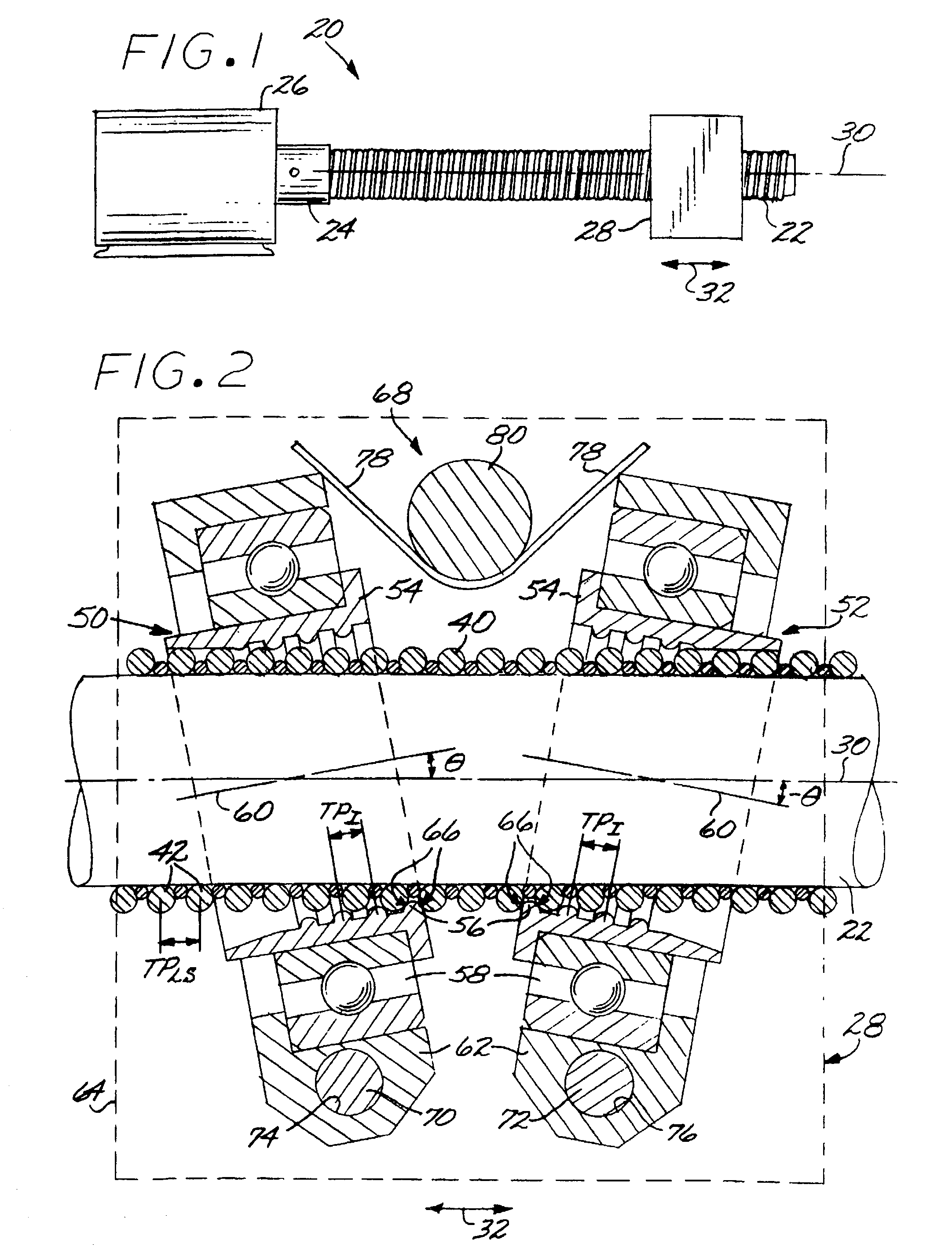
[0014]FIG. 1 depicts a leadscrew mechanical drive 20. The leadscrew mechanical drive 20 includes an externally threaded leadscrew 22 that is driven by a rotational output 24 of a motor 26 or other power source. A leadscrew follower structure 28 is engaged to the leadscrew 22. As the motor 26 turns the leadscrew 22 about its rotational leadscrew axis 30, the threaded engagement between the leadscrew follower structure 28 and the leadscrew 22 translates the rotational movement of the leadscrew 22 into linear movement of the leadscrew follower structure 28 in a linear movement direction 32 parallel to the rotational leadscrew axis 30. The leadscrew follower structure 28 is attached to the structure (not shown) that is to be moved in the linear manner.

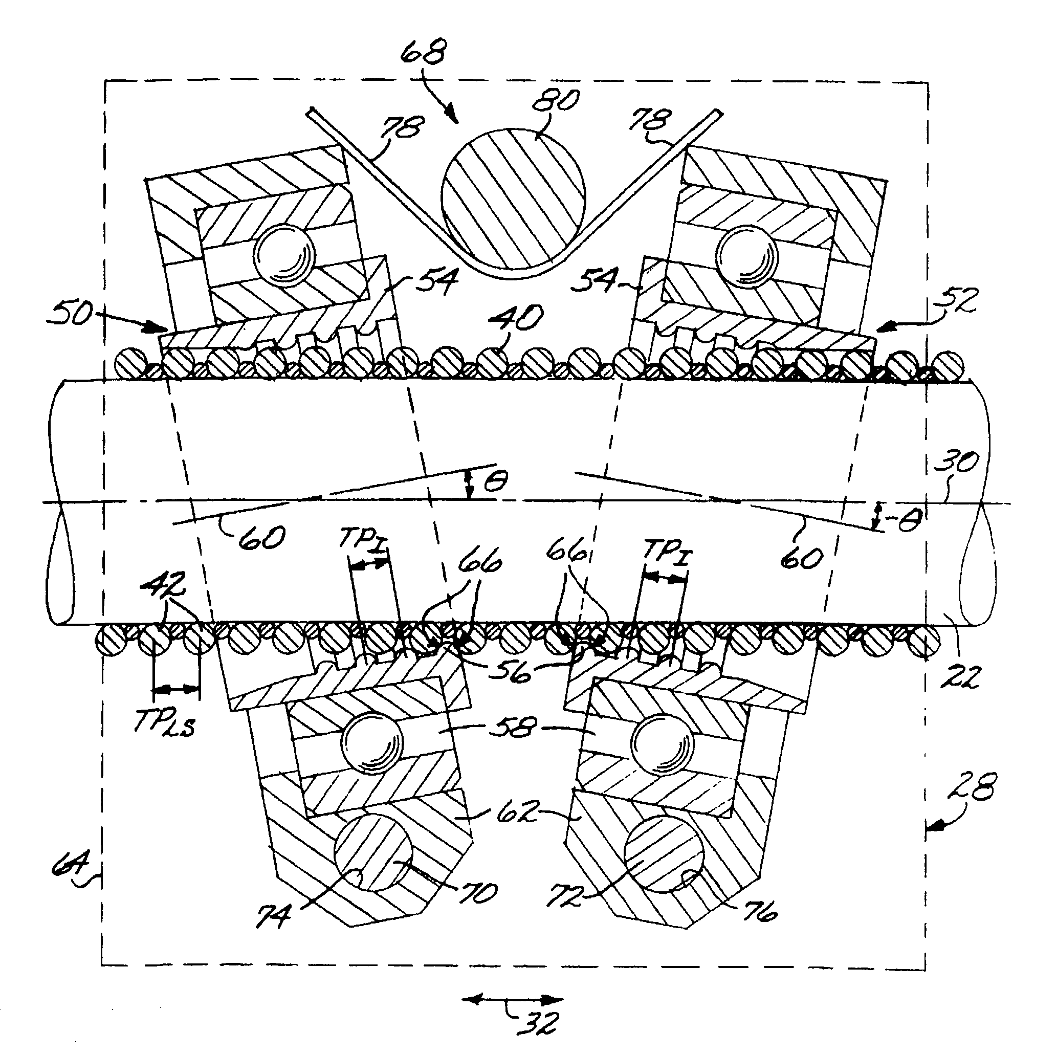
[0015]FIG. 2 schematically depicts the leadscrew 22 and the leadscrew follower structure 28 of a preferred embodiment of the present approach in greater detail. The leadscrew 22 comprises a helical leadscrew thread 40 having a series of tu...


PUM


Abstract

A leadscrew mechanical drive includes a leadscrew having a leadscrew axis and a leadscrew thread with a nonzero leadscrew thread pitch. A leadscrew follower structure preferably having two leadscrew followers is engaged to the leadscrew. Each leadscrew follower includes a threaded insert having an insert thread with a nonzero insert thread pitch different front the leadscrew thread pitch. The insert thread is engaged to the leadscrew thread over a circumferential distance of less than one-half turn of the insert thread. Each leadscrew follower further includes a bearing in which the threaded insert is received and which permits the threaded insert to rotate about an insert axis that is inclined to the leadscrew axis by an angle θ for the first leadscrew follower and −θ for the second leadscrew follower, and a bearing support in which the bearing is received. A preload structure biases each of the leadscrew followers against the leadscrew.

Description

[0001]This invention relates to a leadscrew mechanical drive and, more particularly, to a leadscrew mechanical drive utilizing a leadscrew and a leadscrew follower structure.BACKGROUND OF THE INVENTION[0002]Most common motors have a rotational output, but in many instances the structure to be driven requires a linear motion. There are a number of approaches to mechanically converting the rotational motor output to a linear motion. One such approach is a leadscrew mechanical drive in which the motor rotationally drives a threaded leadscrew. A leadscrew follower structure driven by the leadscrew engages the leadscrew and moves parallel to the axis of the leadscrew to convert the rotational motion to linear motion parallel to the axis of the leadscrew. The leadscrew follower structure typically includes a follower threadably engaged to the leadscrew or a recirculating ball mechanism, although other types of leadscrew followers have been proposed.[0003]The standard leadscrew mechanical ...

Claims


Application Information

Patent Timeline
Patent Type & Authority Patents(United States)
IPC IPC(8): F16H25/24F16H25/22
CPCF16H25/2295Y10T74/18728Y10T74/19805Y10T74/19902Y10T74/1973
Inventor DEVENYI, GABOR
Owner RAYTHEON CANADA LTD
Why Eureka
Try Eureka