Rotary contact structures and cutting elements
a contact structure and cutting element technology, applied in the field of rotary tools, can solve the problems of costing the most, most complex, and the most expensive of the three, and achieve the effects of improving cutting stability, drilling and cutting speed, and reducing the potential for damage to the bi
- Summary
- Abstract
- Description
- Claims
- Application Information
AI Technical Summary
Benefits of technology
Problems solved by technology
Method used
Image
Examples
first embodiment
[0040]FIG. 3 is a partial cross section of a contact structure of the invention and a portion of a projection structure 48 of a cutting element. The contact structure and cutting element are fabricated from one material. This is the simplest embodiment of the present invention. The cross section is taken along the central axis 42 of the contact structure, which is generally radially symmetrical. A tip 44 at the distal end, a tapered face structure 46 extending from the distal end, and part of a projection or mounting structure 48 are shown.
[0041]The tip structure 44 in this embodiment is shown as flat because it is not possible to make a perfect point or edge in any material. Additionally, at some level of size for any given job, sharpness of the point ceases to be a factor in how well the contact structure tip actually cuts or chips material. In any event, it is sometimes advantageous to limit the sharpness of the tip structure 44, as is shown in FIG. 3.
[0042]In the present inventi...
second embodiment
[0045]FIG. 4 shows a contact element 50 and an end of a cutting element of a second embodiment, similar in shape to the contact structure shown in FIG. 3 but fabricated from two different materials. A first material 50, such as polycrystalline diamond or polycrystalline cubic boron nitride, provides or forms the contact element 54, at the tip, and a second material 52, such as cemented metal carbide, which forms the projection structure 56 and the tapered face feature 58. The second material supports the first material 50 through chemical, metallurgical, or mechanical bonding or through an engaging structure (not shown) as in FIG. 8, at 102, below. Welding, sintering, and brazing are suitable methods of attachment also.
[0046]FIG. 5 shows an embodiment of the present invention that includes a contact element column 60 of very hard material, such as polycrystalline diamond or polycrystalline cubic boron nitride, that is configured along the axis 62 of the structure. A second material ...
third embodiment
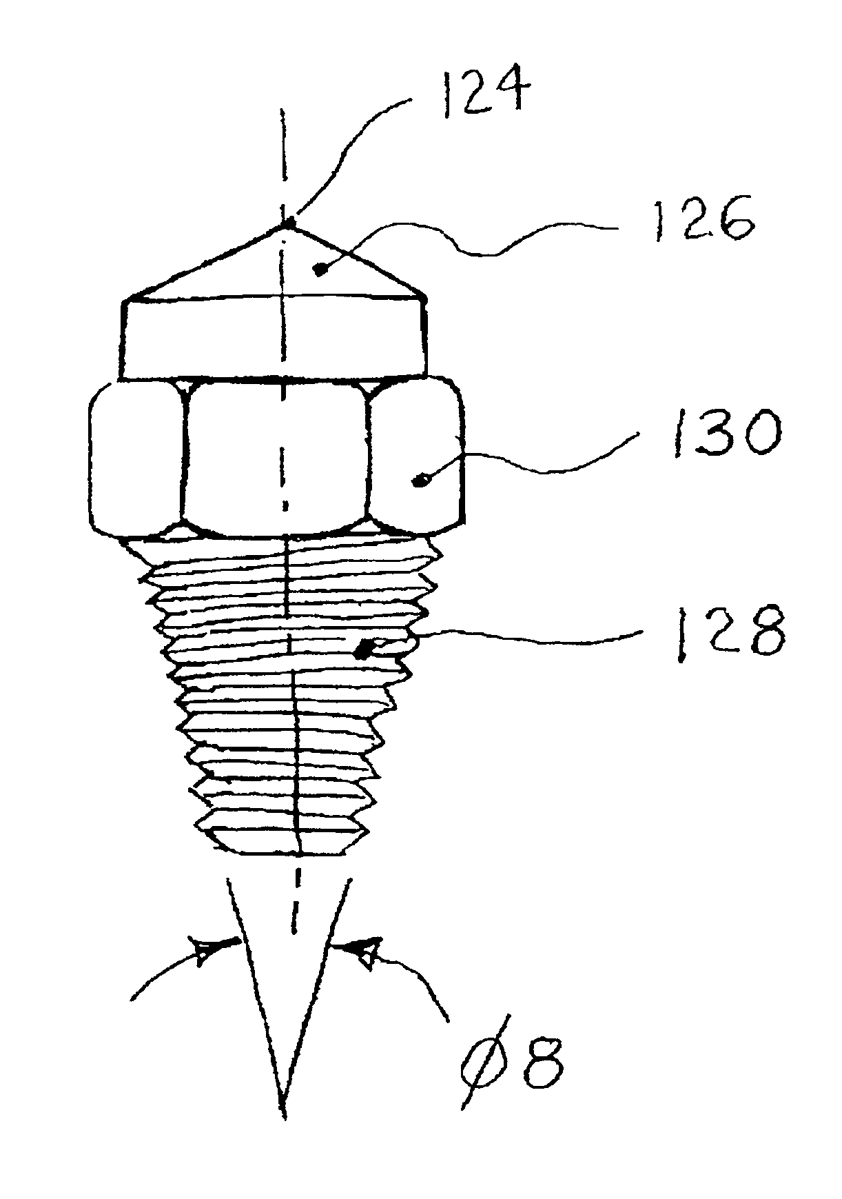
[0055]FIG. 11 shows a contact structure 124, 126 attached to a mounting structure in the invention. The mounting structure comprises a threaded element 128 and a circumferentially engageable element 130, which permits grasping and turning the element, as with a wrench. The threaded element 128 is tapered at an angle Φ8. The tapered form of the threaded element 128 allows cutting elements to be assembled more closely to each other in a bit assembly. The increased cutting element density helps stabilize the bit while cutting, by distributing the imposed loads. It also allows for the alignment of cutting elements in rows. An additional advantage of the tapered, threaded holding structure 128 is that it is self-locking. In the present invention the angle Φ8 is between ½ degree and 60 degrees. The circumferentially engageable feature 130 is a hexagon, but other forms can be used. Cutting elements that are threadably engageable as in FIG. 11 are fixed and are not rotatable. The cutting el...
PUM
 Abstract
Description
Claims
Application Information
 - R&D
- Intellectual Property
- Life Sciences
- Materials
- Tech Scout
- Unparalleled Data Quality
- Higher Quality Content
- 60% Fewer Hallucinations
Browse by: Latest US Patents, China's latest patents, Technical Efficacy Thesaurus, Application Domain, Technology Topic, Popular Technical Reports.
© 2025 PatSnap. All rights reserved.Legal|Privacy policy|Modern Slavery Act Transparency Statement|Sitemap|About US| Contact US: help@patsnap.com


