Flushing position controller incorporated in ink-jet recording apparatus and flushing method used for the same

a technology of inkjet recording apparatus and flushing method, which is applied in printing and other directions, can solve the problems of ink-jet recording head problems, increase in the viscosity of ink, printing failures, etc., and achieve the effect of preventing a decrease in throughpu

Inactive Publication Date: 2005-08-23
SEIKO EPSON CORP
View PDF10 Cites 16 Cited by
  • Summary
  • Abstract
  • Description
  • Claims
  • Application Information

AI Technical Summary

Benefits of technology

[0049]In view of the above, a first object of the present invention is to provide an ink-jet recording appar

Problems solved by technology

The ink-jet recording head suffers problems such as printing failures, which are caused by an increase in the viscosity of ink due to evaporation of a solvent by way of nozzle orifices, solidification of ink, adhesion of dirt or dust to the nozzles, or mixing of air bubbles into ink.
Because of these requirements, the related recording apparatus encounters technological problems; i.e., a deterioration in throughput associated with the flushing operation; and an increase in print time.
If the recording head is to be flushed while situated at the non-print region opposite the capping member, the carriage must temporarily travel to the capping member, thus considerably deteriorating throughput.
However, in some cases the ink-absorbing member cannot be disposed opposite the flushing region, because of a limitation imposed by the layout of other components.
In a recent recording apparatus which controls the quantity of single ink droplets so as to form the smallest-possible ink droplets in order to implement high picture quality, the foregoing problems become more pronounced.
However

Method used


Image

  • Flushing position controller incorporated in ink-jet recording apparatus and flushing method used for the same
  • Flushing position controller incorporated in ink-jet recording apparatus and flushing method used for the same
  • Flushing position controller incorporated in ink-jet recording apparatus and flushing method used for the same

Examples


first embodiment

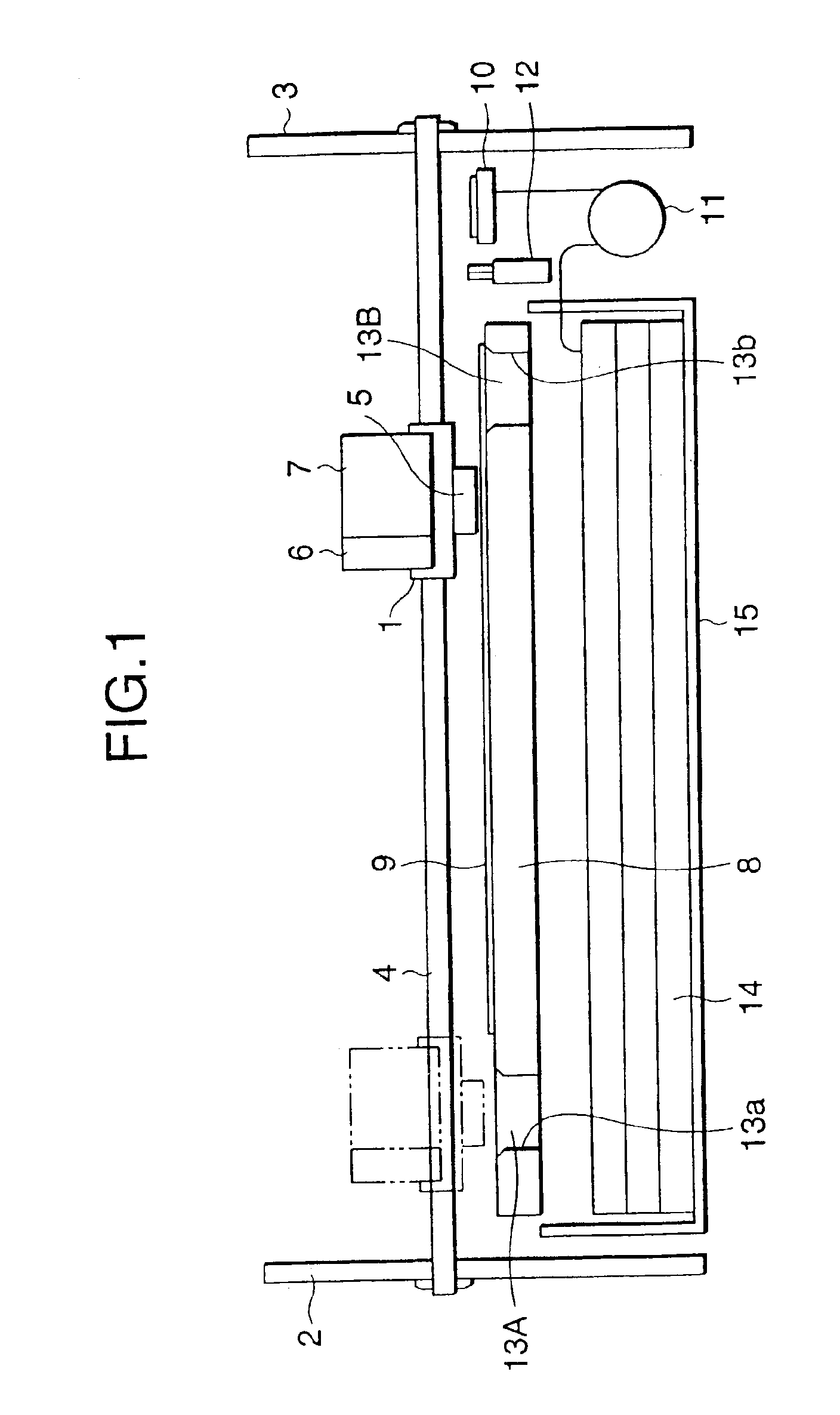
[0166]To start, an ink-jet recording apparatus according to the present invention will now be described by reference to FIGS. 1 and 2.

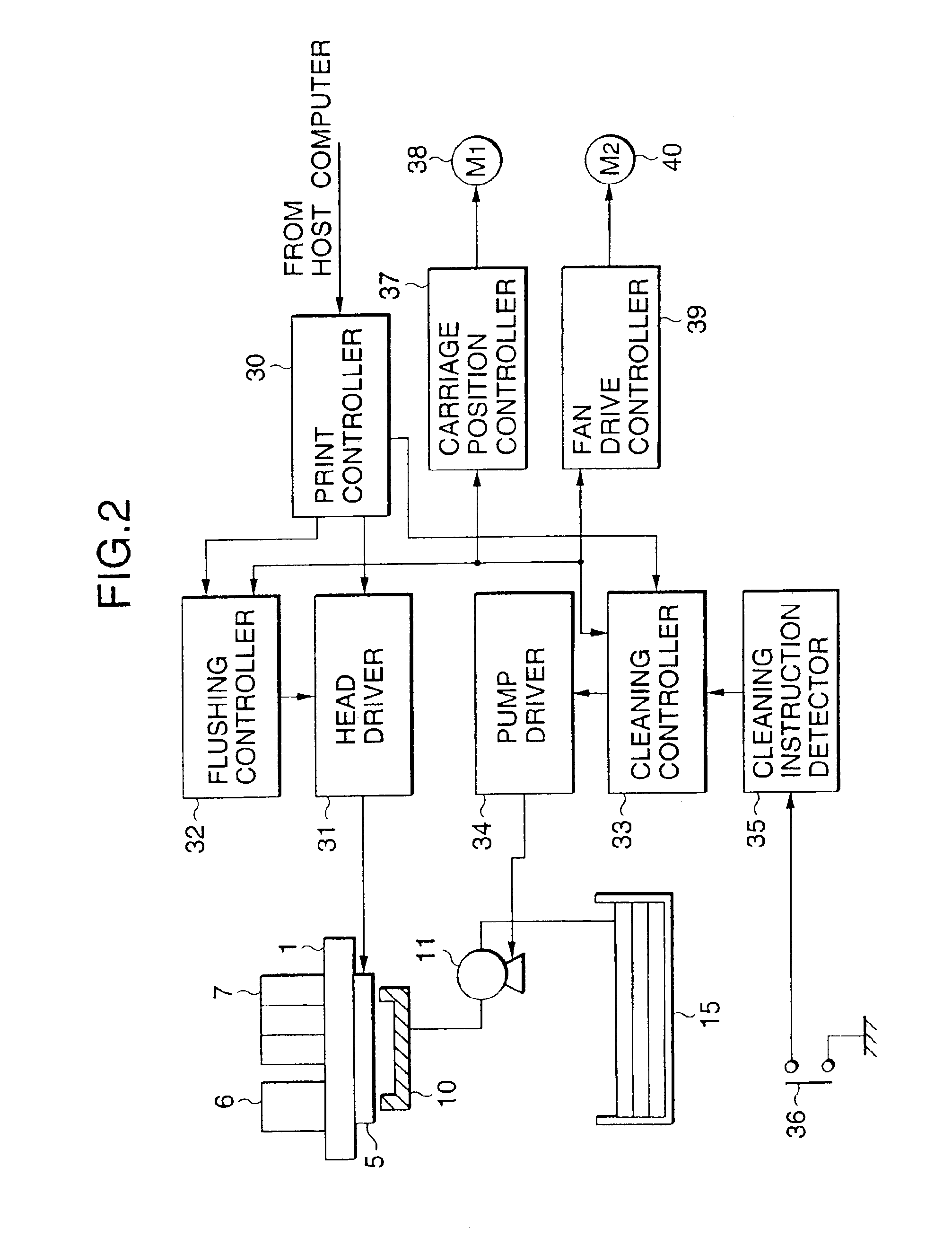
[0167]FIG. 1 shows configuration of a main unit of an ink-jet recording apparatus according to a first embodiment of the present invention, and FIG. 2 shows an example of a control circuit provided in the recording apparatus.

[0168]In FIGS. 1 and 2, the elements which are identical with or correspond to those shown in FIG. 19 are assigned the same reference numerals, and repetition of their detailed explanations is omitted here for brevity.

[0169]The ink-jet recording apparatus according to the first embodiment is characterized in that flushing regions 13A and 13B for receiving ink droplets to be ejected when a flushing drive signal is supplied to a recording head 5 are disposed in non-print regions such that the flushing region 13A is provided in the non-print region where capping member 10 for sealing the recording head is disposed and the flushing re...

second embodiment

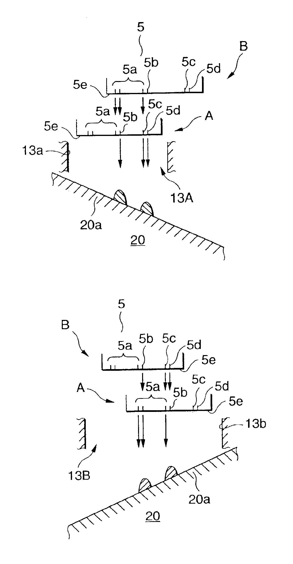
[0185]An ink-jet recording apparatus according to the present invention will now be described by reference to FIGS. 3 and 4.

[0186]FIG. 3 shows the configuration of a main unit of the recording apparatus according to the second embodiment, and FIG. 4 is an enlarged view of the flushing region shown in FIG. 3.

[0187]In FIGS. 3 and 4, the elements which are identical with or correspond to those shown in FIGS. 1 and 2 are assigned the same reference numerals, and repetition of their detailed explanations is omitted here for brevity.

[0188]Since the control circuit of the recording apparatus is identical with that shown in FIG. 2, repetition of its explanation is omitted.

[0189]As shown in FIG. 3, the ink-jet recording apparatus of the second embodiment is characterized in that slant members 20, each having a slant surface 20a tilted toward the print region, are interposed such the one slant member 20 is interposed between the aperture 13a formed in the paper guide member 8 provided in the ...

third embodiment

[0218]An ink-jet recording apparatus according to the present invention will now be described.

[0219]FIGS. 6 and 7 show the configuration of a large-sized ink-jet recording apparatus (hereinafter also called “printer”) installed directly on the floor. FIG. 6 is a perspective outline of the printer, and FIG. 7 is a front view showing the internal configuration of the printer.

[0220]FIG. 8 is a longitudinal cross-sectional view of the printer shown in FIG. 7 taken through a flushing region to be described later.

[0221]In this printer are arranged a paper feed section 101, a print section 102, and a paper output section 103, in this order from top to bottom.

[0222]A paper transport channel is formed into a substantially linear path which is tilted relative to the vertical line and extends from the paper feed section 101 to the paper output section 103 by way of the print section 102.

[0223]As shown in FIGS. 7 and 8, long roll paper 104 having a width of, for example, up to 40 inches can be ...


PUM


Abstract

Flushing regions for receiving ink droplets to be ejected when flushing signal is supplied to a recording head are provided in both of non-print regions situated at both sides of print region in order to prevent throughput during the flushing operation from deteriorating. A guide member having a slant surface is disposed between the recording head and an ink absorbing member to which the ink landed on the slant surface flows in order to reduce in size of the ink absorbing member. A porous sheet member closely faced to nozzle orifices of the recording head for receiving the ink droplets ejected therefrom is provided in order to prevent undesired mist of fine ink droplets from generating. A plurality of plate members closely faced to the nozzle orifices are provided at a predetermined angle with respect to the flight direction of the ink droplets in order to prevent the undesired mist from generating. The flushing operation is performed so as to prevent solidification of the ejected ink.

Description

CROSS-REFERENCE TO RELATED APPLICATION[0001]This is a continuation application of U.S. patent application No. 09 / 747,930 filed Dec. 27, 2000 now U.S. Pat. No. 6,619,783, which application was a continuation-in-part of U.S. patent application No. 09 / 443,299 filed Nov. 19, 1999 now abandoned, the disclosure of both previous applications being incorporated in full herein by reference.BACKGROUND OF THE INVENTION[0002]The present invention relates to a flushing position controller incorporated in an ink-jet recording apparatus and a flushing method used for the same. More particularly, the present invention relates to an ink-jet recording apparatus comprising an ink-jet recording head which is mounted on a carriage so as to travel in the widthwise direction of recording paper and which forms an image on a recording medium by ejecting jets of ink droplets via nozzle orifices, and a flushing region provided on the path along which the recording head travels for receiving ink droplets to be...

Claims


Application Information

Patent Timeline
IPC IPC(8): B41J2/17B41J2/165
CPCB41J2/16508B41J2/1721B41J2002/1728B41J2002/1742
Inventor KANAYA, MUNEHIDEHARA, KAZUHIKOFUKASAWA, SHIGENORIKOBAYASHI, ATSUSHISUZUKI, KAZUNAGA
Owner SEIKO EPSON CORP
Why Eureka
Try Eureka