Device for controlling a forager chute

a technology for a chute and a control device, which is applied in the direction of refuse transferring, harvesting machines, applications, etc., can solve the problems of difficult monitoring of the transfer device for the driver, limiting the pivot range, and inability to continue the pivoting of the transfer device in most harvesting machines. , to achieve the effect of a larger pivot range and more comfortable operation

Active Publication Date: 2005-08-23
CLAAS SELBSTFAHRENDE ERNTEMASCHINEN GMBH
View PDF6 Cites 47 Cited by
  • Summary
  • Abstract
  • Description
  • Claims
  • Application Information

AI Technical Summary

Benefits of technology

[0009]It is in view of the above problems that the present invention was developed. The invention is a control device and a method for controlling a transfer device on a harvesting machine. The device and method allow for more comfortable operation and monitoring of the transfer device by the driver. The driver is thereby relieved of stress by the resulting extended possibilities of adjustment during the control and monitoring of the transfer device. Further, due to the larger pivot range, more flexible adaptation of the transfer device to the parallel-driving transport vehicle is possible.

Problems solved by technology

Unfortunately, continuous pivoting of the transfer device is not possible in most harvesting machines because housing parts of the harvesting machine, for example the driver's cab, protrude upwards above the plane in which the planetary gear is arranged.
This limiting of the pivot range has a particularly adverse effect in forage harvesters in which usually an upper discharge chute is arranged as the transfer device a relatively short distance behind the driver's cab.
As a result of this greatly restricted pivot range of the transfer device, monitoring of the transfer device is made difficult for the driver.
Hence, these items are not readily variable to extend the pivot range.
Similarly, it is not desirable to alter the position of the driver's cab either.
Reducing the depth of the driver's cab would impair the driver's comfort.
Other drawbacks are associated with this type of alteration.

Method used


Image

  • Device for controlling a forager chute
  • Device for controlling a forager chute
  • Device for controlling a forager chute

Examples


Embodiment Construction

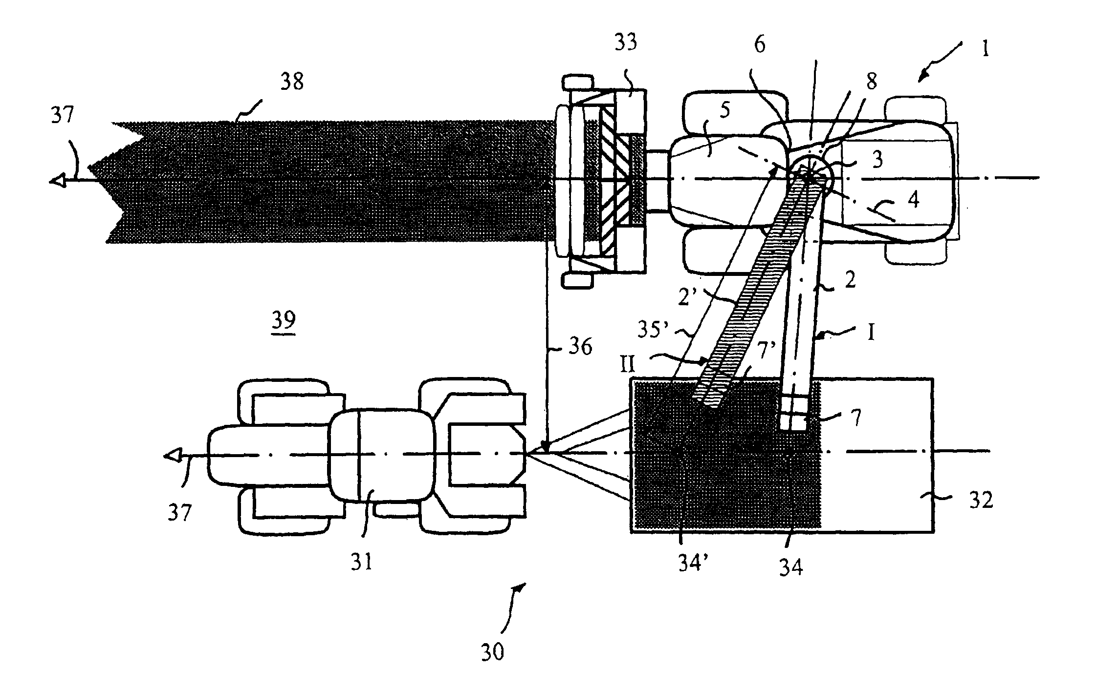
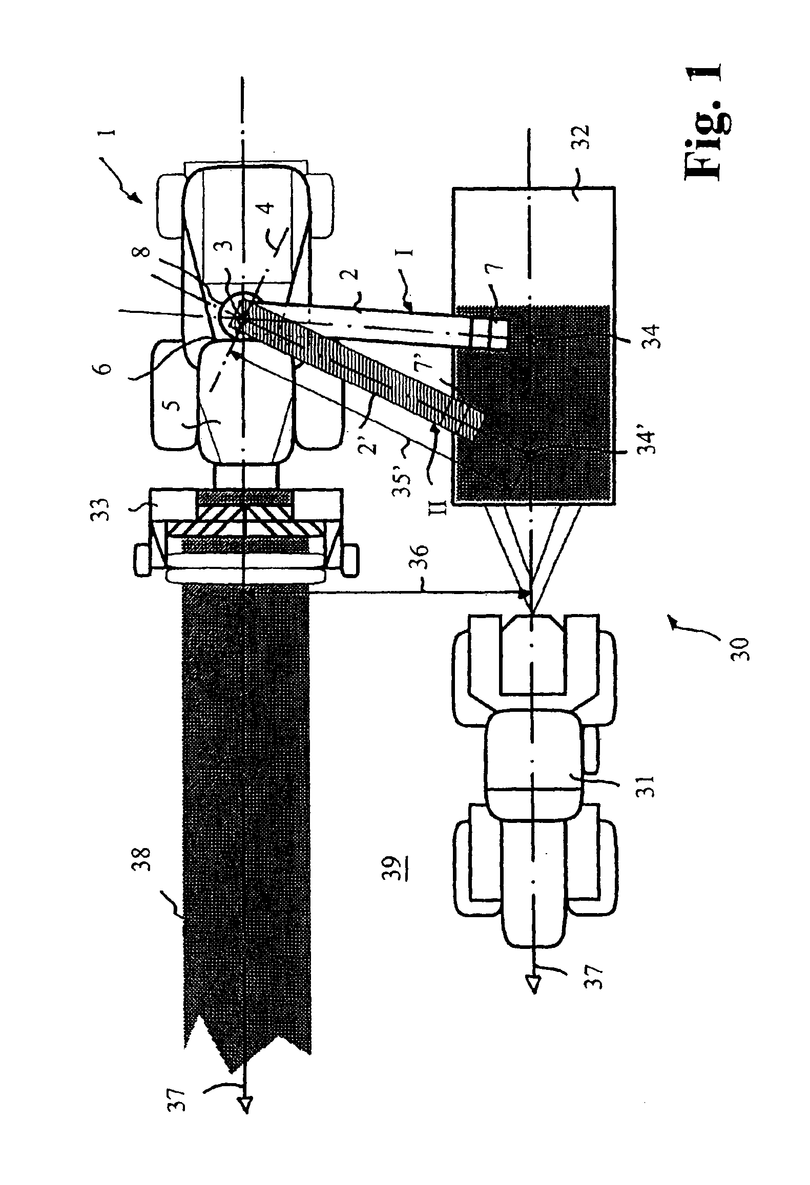
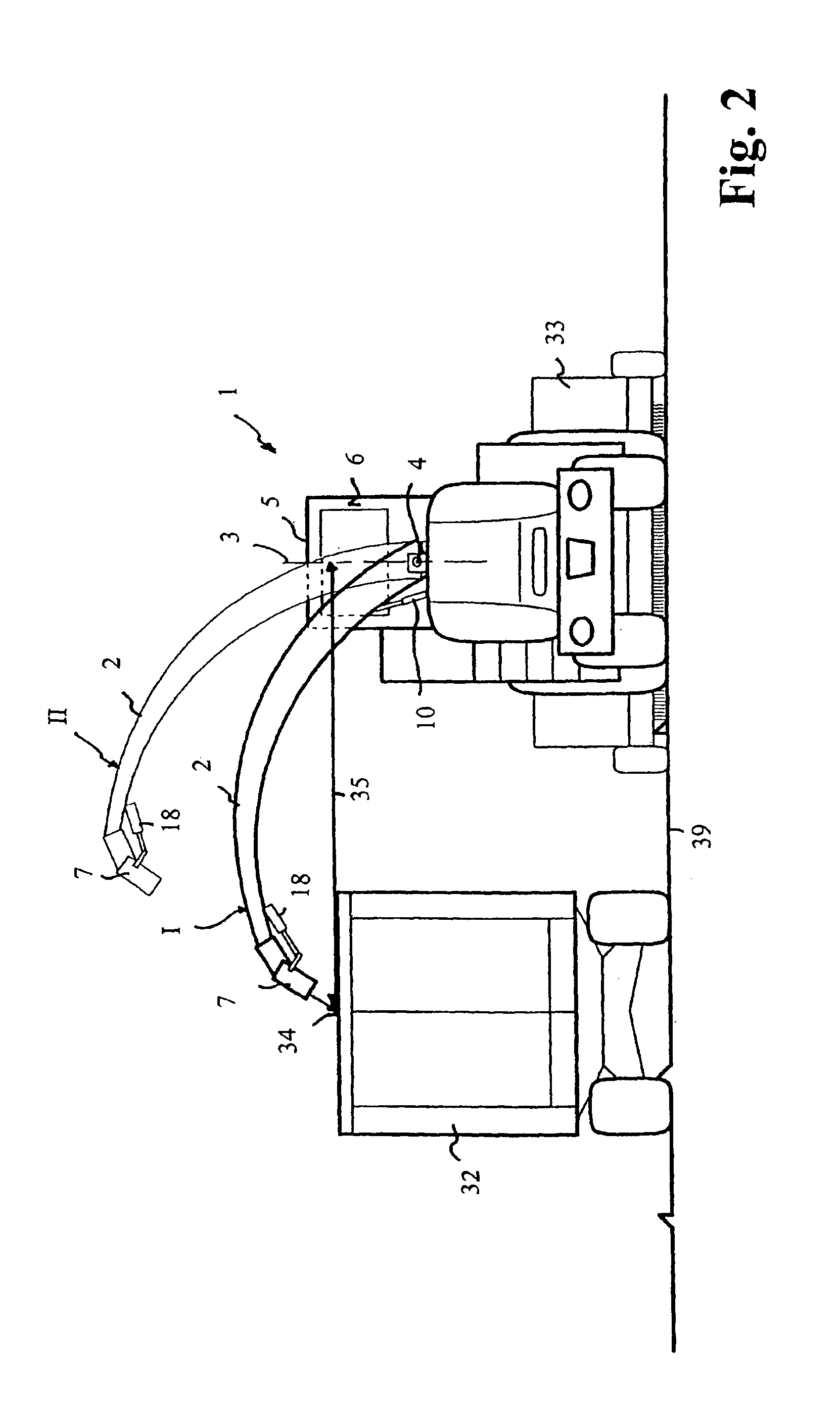
[0020]In the practical examples shown in FIGS. 1 and 2, a harvesting machine 1 is shown as a forage harvester which collects grass swaths 38 continuously by means of a front pick-up attachment 33. The grass is chopped in the forage harvester 1 and transferred by means of an upper discharge chute 2 to a parallel-driving transport vehicle 30. The transport vehicle 30 here is a tractor 31 which pulls along a transport trailer 32 beside the forage harvester 1. The upper discharge chute 2, also known as a transfer device, is arranged directly behind a housing part 5, such as the driver's cab. The discharge chute 2 is pivotable in the usual manner about a vertical axis of rotation 3 and, to alter a height setting, about a horizontal axis 4.

[0021]The upper discharge chute 2 is shown in FIGS. 1 and 2 in two different positions I, II respectively. In the first position I, the upper discharge chute 2 is located at a lower height setting, at which a discharge end of the upper discharge chute 2...


PUM


Abstract

A control device and corresponding method for controlling a transfer device on a harvesting machine are disclosed. The transfer device is arranged at a distance adjacent to a housing part so as to be rotatable about a vertical axis and, to alter the height setting, elevatable about a horizontal axis. The control device includes a rotation range limiting means that limits the maximum permitted pivot range of the transfer device as a function of the height setting of the transfer device.

Description

CROSS REFERENCE TO RELATED APPLICATION[0001]This application claims priority of German Application DE 102 40 219.1 filed Aug. 28, 2002.STATEMENT REGARDING FEDERALLY SPONSORED RESEARCH[0002]NoneBACKGROUND OF THE INVENTION[0003]The present invention relates generally to harvesting machines and more particularly to a control device for controlling a transfer device on a harvesting machine, wherein the transfer device is arranged so as to be pivotable about a vertical axis and, to alter a height setting, about a horizontal axis.[0004]Self-propelled harvesting machines, for example forage harvesters, combine harvesters, sugar cane harvesting machines and the like, usually have a transfer device, e.g. an upper discharge chute, a grain tank unloading tube, a conveyor chain or a conveyor belt, with which the crop is transferred from the harvesting machine to a transport vehicle. When the harvested crop is to be transferred continuously during a harvesting journey, for example in the case of...

Claims


Application Information

Patent Timeline
Patent Type & Authority Patents(United States)
IPC IPC(8): A01D43/07A01D43/00A01D43/08
CPCA01D43/07A01D43/087
Inventor ISFORT, HEINRICHPOLIKLAS, MANFRED
Owner CLAAS SELBSTFAHRENDE ERNTEMASCHINEN GMBH
Why Eureka
Try Eureka