Wind power installation

a technology for wind power installation and wind power, applied in wind power motors with parallel air flow, non-positive displacement fluid engines, liquid fuel engine components, etc., can solve the problems of not being able to protect the entire electronic installation device, other electronic devices of the wind power installation are also affected, etc., to reduce the number of interferences

Inactive Publication Date: 2005-08-23
WOBBEN ALOYS
View PDF9 Cites 48 Cited by
  • Summary
  • Abstract
  • Description
  • Claims
  • Application Information

AI Technical Summary

Benefits of technology

[0006]An object of the present invention is to reduce the number of interferences

Problems solved by technology

These abrupt discharges which are not due to a lightning strike because of a storm but due to electrostatic charging of the rotors interfere with the entire electronic system of the wind power installation, which is in the area around the flash-over, such as for example the computers or microprocessors which control and regulate an individual rotor blade.
However other electroni

Method used


Image

  • Wind power installation
  • Wind power installation
  • Wind power installation

Examples


Embodiment Construction

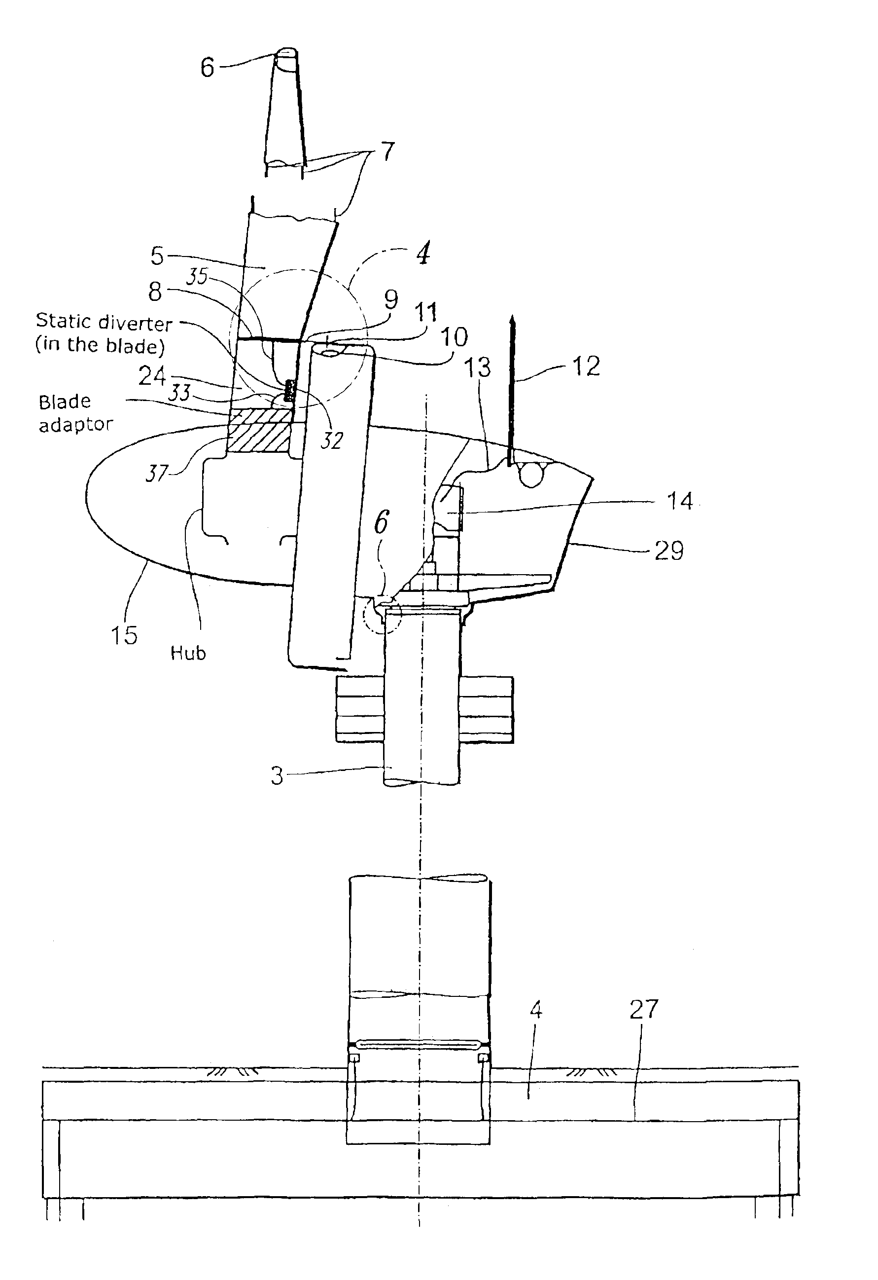
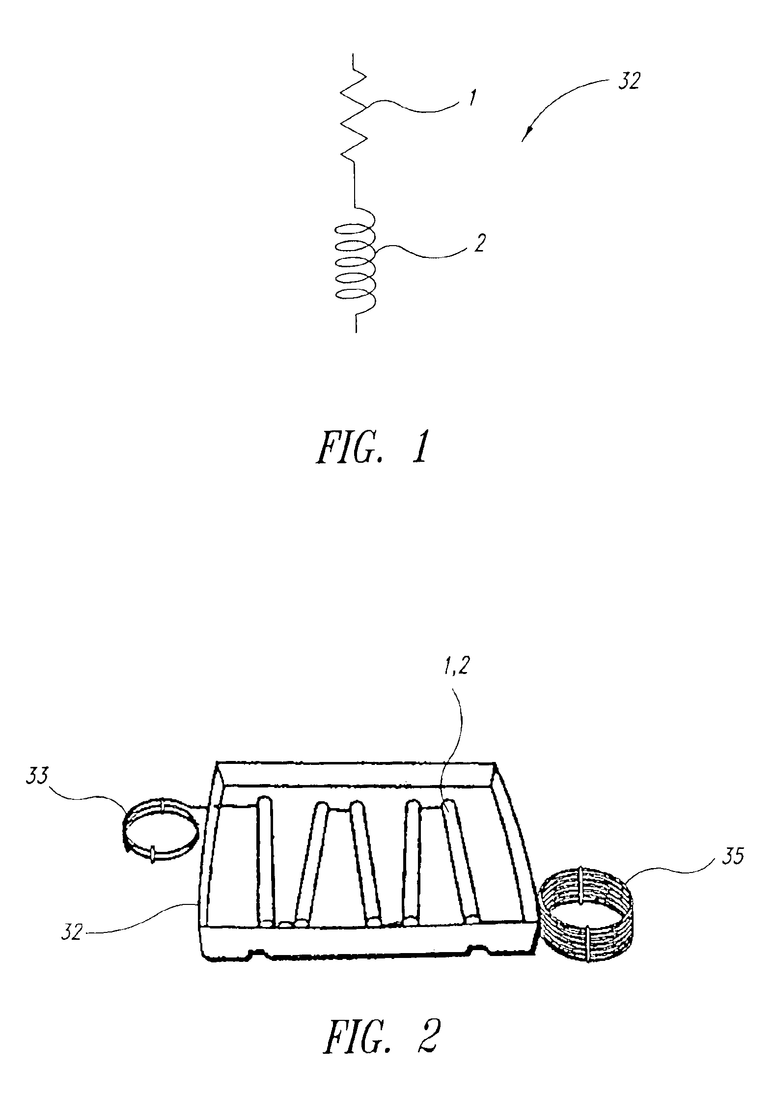
[0015]It is particularly desirable if the arrangement for continuously discharging electrostatic charging of the rotor blades comprises a discharging circuit 32 which has a series circuit of an ohmic diverter resistor 1. In one embodiment, it may also include an inductor 2. This is shown in FIG. 1. In this case the diverter resistor 1 is preferably of a value of about 50 KΩ and the inductor 2 is preferably of a value of 10 μH or more.

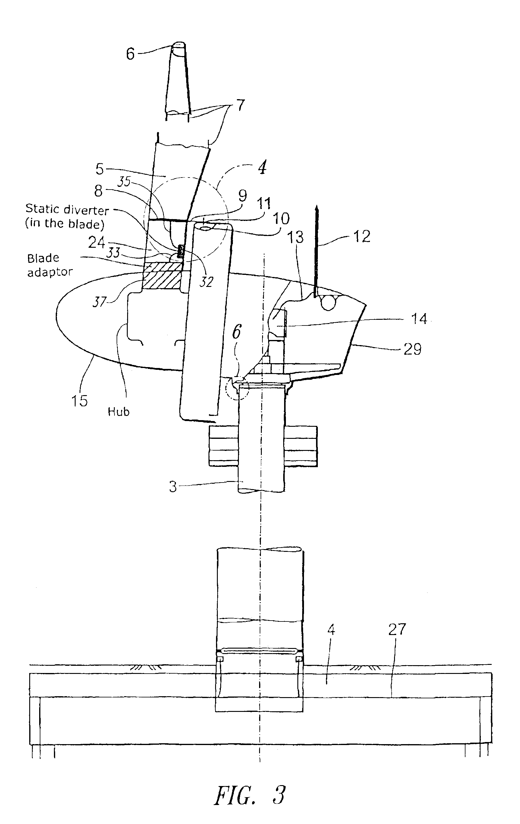
[0016]During static discharging of the rotor blades 5 the inductor 2 is not in operation as the diverter current represent a direct current of very small amplitude. This means that each rotor blade 5 is connected for static discharging with a resistor 1 of 50 kΩ to an earth potential when the circuit shown in FIG. 1 connects a rotor blade 5 to the earth connection of the earth potential.

[0017]In the case of a lightning strike (because of a storm) the voltage at the spark gap (the discharge circuit shown in FIG. 1) rises very high. The magnitude of the v...


PUM


Abstract

The invention concerns a wind power installation. Such wind power installations of modern type, for example one of type E-40 or E-66 from Enercon are usually equipped with a lightning protection system which is known for example from DE 44 36 197.
The present invention assists to minimise the number of interference with the electronic system by virtue of the flash-over effects at the spark path. A wind power installation comprising an arrangement for continuously discharging electrostatic charging of at least one rotor blade of a wind power installation.

Description

BACKGROUND OF THE INVENTION[0001]1. Field of the Invention[0002]The invention concerns a wind power installation and in particular electrostatic discharge protection of such wind power installation.[0003]2. Description of the Related Art[0004]Wind power installations of modern type, for example one of type E-40 or E-66 from Enercon are usually equipped with a lightning protection system which is known for example from DE 44 36 290, DE 198 26 086, DE 195 01 267, DE 44 45 899, WO 00 / 14405 or WO 96 / 07825.[0005]In the case of such lightning protection systems like the known systems described hereinbefore, when the rotor blade is galvanically separated from the hub the respective rotor blade can be statically charged up. That electrostatic charging of a rotor blade occurs due to the friction of the air against the rotating rotor blade of a rotor of a wind power installation. Depending on the respective air humidity or other disadvantageous weather influences the rotor blades (or the ligh...

Claims


Application Information

Patent Timeline
IPC IPC(8): F03D1/00F03D11/00F03D1/06H02G13/00H01T1/22H01T4/00H02P9/00H05F3/02H05F3/04
CPCF03D1/065F03D11/00F03D11/0033H02G13/00H02G13/80H02G13/40F05B2240/30Y02E10/721Y02E10/722F03D80/00F03D80/30Y02E10/72
Inventor WOBBEN, ALOYS
Owner WOBBEN ALOYS
Why Eureka
Try Eureka