OLED display with photosensor

a technology of oled display and photosensor, which is applied in the direction of roof drainage, organic semiconductor devices, electroluminescent light sources, etc., can solve the problems of reducing the light emitted by half, reducing the light output by half, and not being able to provide real-time operation, etc., and achieves the effect of maximizing the light outpu

Inactive Publication Date: 2005-08-23
GLOBAL OLED TECH
View PDF5 Cites 153 Cited by
  • Summary
  • Abstract
  • Description
  • Claims
  • Application Information

AI Technical Summary

Benefits of technology

[0009]The advantages of this invention are an OLED display device that provides a means

Problems solved by technology

However, as the display is used, the organic materials in the device age and become less efficient at emitting light.
If the portion of the light emitted toward the back is absorbed, it is absorbed and lost, thereby reducing the light emitted by one half.
This approach has the problem that the sensor device obscures the display during the calibration and is not cap

Method used


Image

  • OLED display with photosensor
  • OLED display with photosensor
  • OLED display with photosensor

Examples


Embodiment Construction

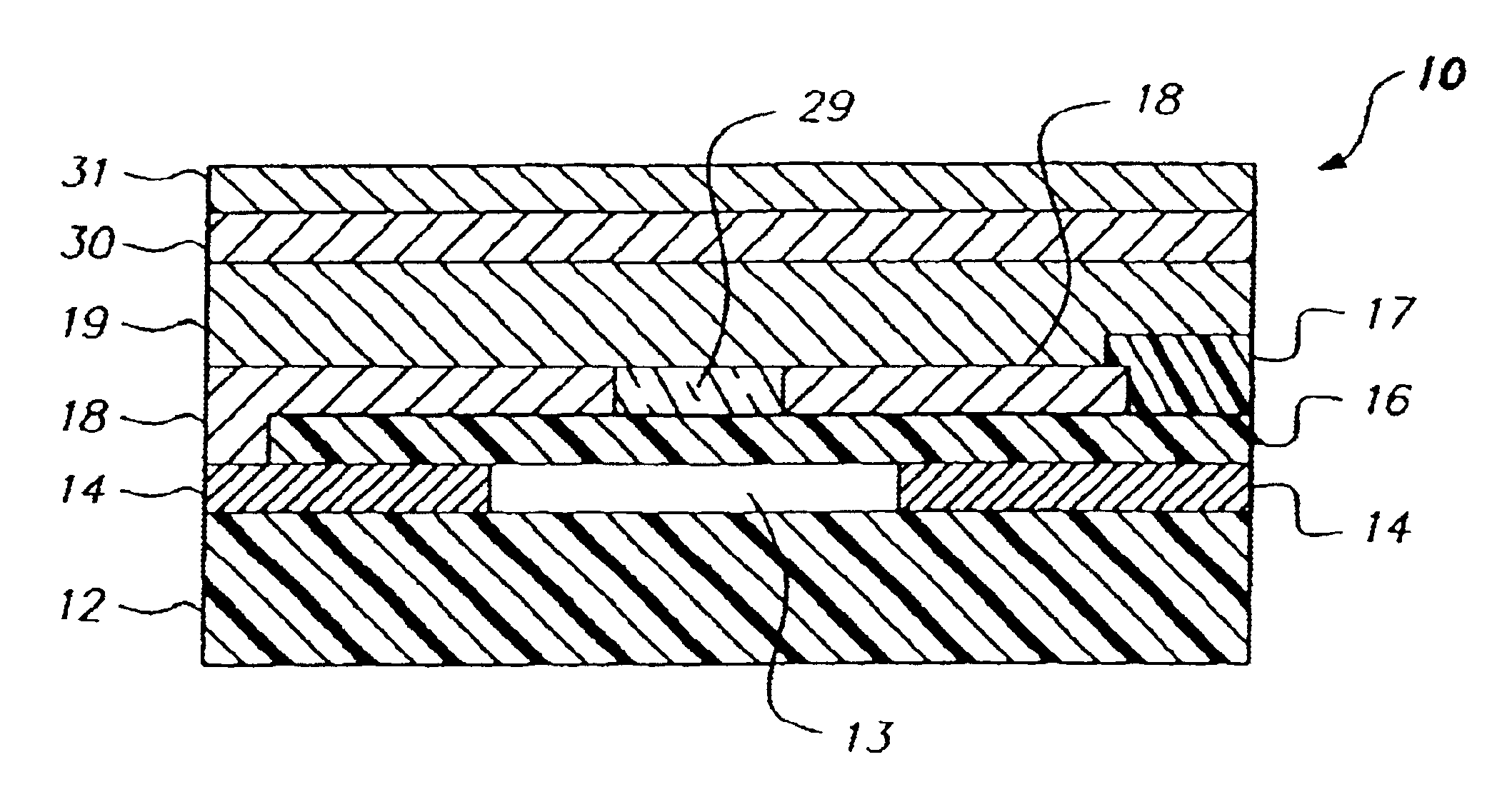
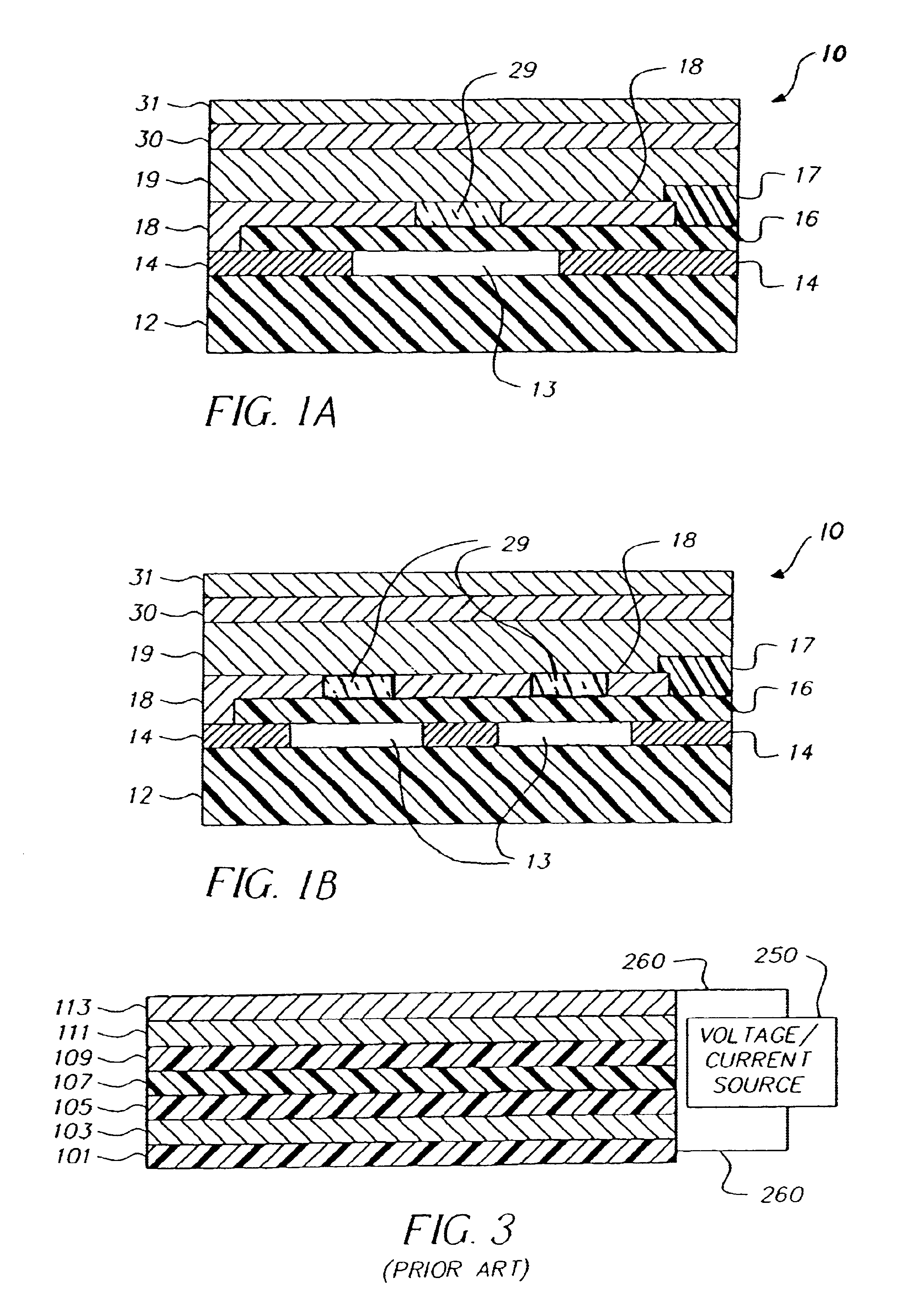
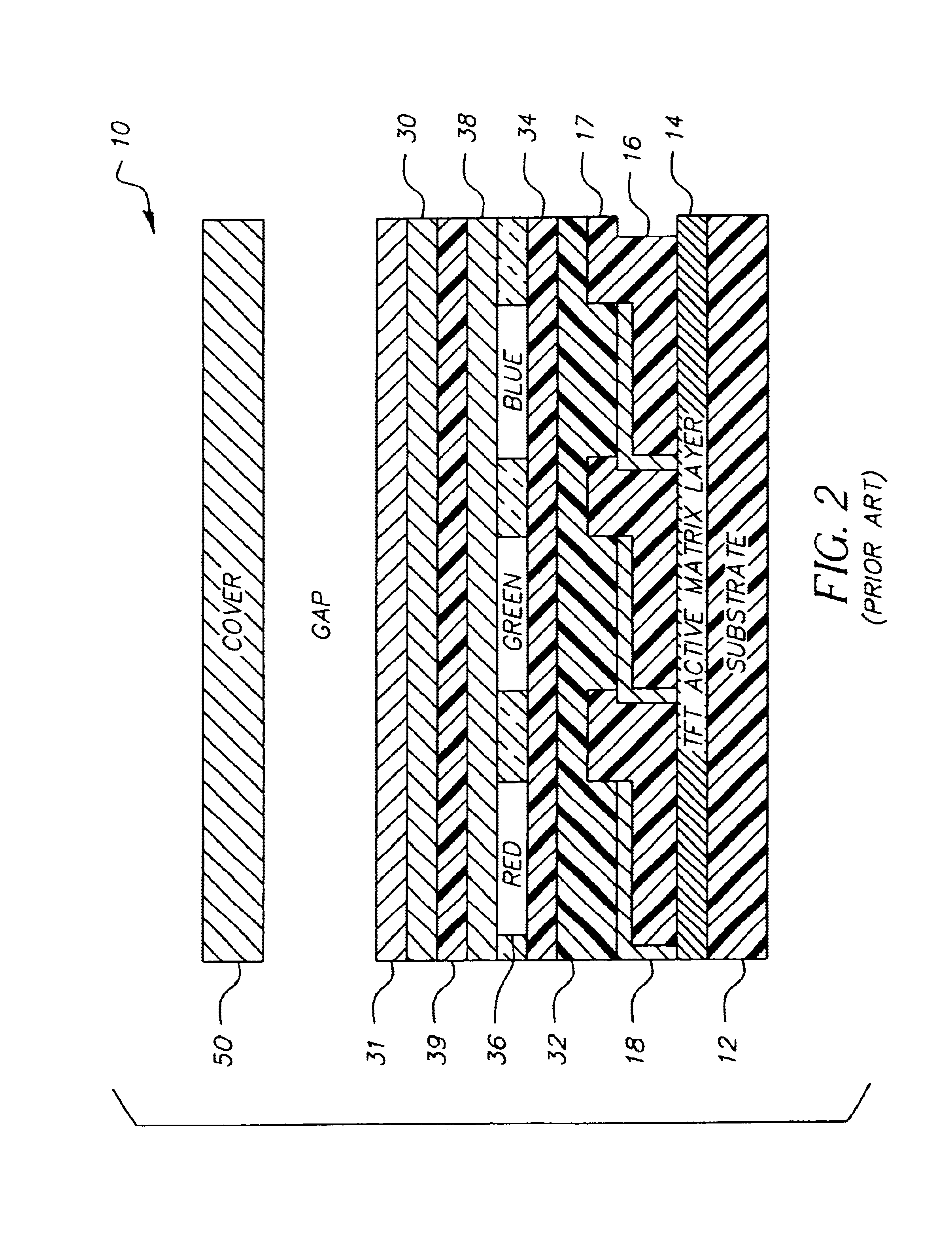
[0013]Referring to FIG. 2, a prior art top-emitting OLED display device 10 is shown with a substrate 12, and a thin-film transistor (TFT) active matrix layer 14 comprising an array of TFTs that provides power to OLED elements. A patterned first insulating layer 16 is provided over the TFT active matrix layer 14, and an array of reflective electrodes 18 are provided over insulating layer 16 and in electrical contact with the TFT active matrix layer 14. A patterned second insulating layer 17 is provided over the array of reflective electrodes 18 such that at least a portion of the each of the reflective electrodes 18 is exposed.

[0014]Over the first electrodes and insulating layers are provided red, green, and blue-emitting organic electroluminescent (EL) elements 19. Herein, the collection of organic EL elements may also be referred to as the organic EL layer. This layer may be made up of other layers as is known in the art, for example a hole-injection layer 32, hole-transport layer ...


PUM


Abstract

An OLED display including: a transparent electrode; a reflective electrode having a transparent window; a light emissive layer disposed between the transparent electrode and the reflective electrode; and a photosensor located under the transparent window of the reflective electrode to sense light produced by the light emissive layer.

Description

FIELD OF THE INVENTION[0001]The present invention relates to solid-state OLED flat-panel displays and more particularly to such displays having photosensors integrated into the display.BACKGROUND OF THE INVENTION[0002]Solid-state organic light emitting diode (OLED) image displays are of great interest as a superior flat-panel display technology. These displays utilize current passing through thin films of organic material to generate light. The color of light emitted and the efficiency of the energy conversion from current to light are determined by the composition of the organic thin-film material. Different organic materials emit different colors of light. However, as the display is used, the organic materials in the device age and become less efficient at emitting light. It is useful, therefore, to provide a means to correct the light output of an OLED device over time.[0003]OLED devices are conventionally either top-emitting or bottom-emitting. An OLED display is constructed upo...

Claims


Application Information

Patent Timeline
IPC IPC(8): H01L27/32H01L51/52H01L27/28H01L51/50H05B33/02H05B33/00H05B33/26
CPCH01L27/3269H01L51/5203H01L2251/5315H10K59/13H10K2102/3026H10K59/805E04D13/08E04D2013/084H10K50/805
Inventor ARNOLD, ANDREW D.COK, RONALD S.
Owner GLOBAL OLED TECH
Why Eureka
Try Eureka