Circuit arrangement and method for starting and operating discharge lamps

a discharge lamp and circuit arrangement technology, applied in the direction of light sources, lighting apparatus, instruments, etc., can solve the problems of main energy store destruction, optimization problems, and energy received by the circuit arrangement, and achieve the effect of reliable ignition

Inactive Publication Date: 2005-08-23
PATENT TREUHAND GESELLSCHAFT FUR ELECTRIC GLUEHLAMPEN MBH
View PDF5 Cites 12 Cited by
  • Summary
  • Abstract
  • Description
  • Claims
  • Application Information

AI Technical Summary

Benefits of technology

[0029]The circuit arragement should accomplish a reliable and low-cost ignition of the lamp.
[0035]By choosing the threshold value and the frequency increase, it is possible to set the maximum energy imbalance in the charge pump. According to the invention, a maximum ignition voltage can consequently be achieved along with optimum use of the components. Consequently, reliable ignition of discharge lamps is possible even with low-cost components.

Problems solved by technology

If the main energy store is charged directly from the rectifier, this produces charge current peaks, which lead to infringement of said regulations.
In this case, the following problem occurs: before the igniting of the discharge lamp, on the one hand there is no significant energy consumer in the circuit arrangement.
This produces an imbalance between the energy received by the circuit arrangement and the energy delivered by it.
If the discharge lamp does not ignite promptly, this leads either to the main energy store being destroyed or to the circuit arrangement being switched off, if switching-off means are provided for this purpose.
In the prior art, this leads to an optimization problem for the choice of the inverter frequency during the igniting phase: On the one hand, the time in which said energy imbalance prevails is to be short.
The optimizing task is made more difficult by the fact that external circumstances, such as for example the igniting properties of the discharge lamp, ambient temperature and component tolerances, have an influence on it.
In the prior art, there are two solutions to the problem: either unreliable ignition of the discharge lamp is accepted, or components such as the main energy store and lamp inductor are overdimensioned, and consequently become expensive and bulky.

Method used


Image

  • Circuit arrangement and method for starting and operating discharge lamps
  • Circuit arrangement and method for starting and operating discharge lamps
  • Circuit arrangement and method for starting and operating discharge lamps

Examples


Embodiment Construction

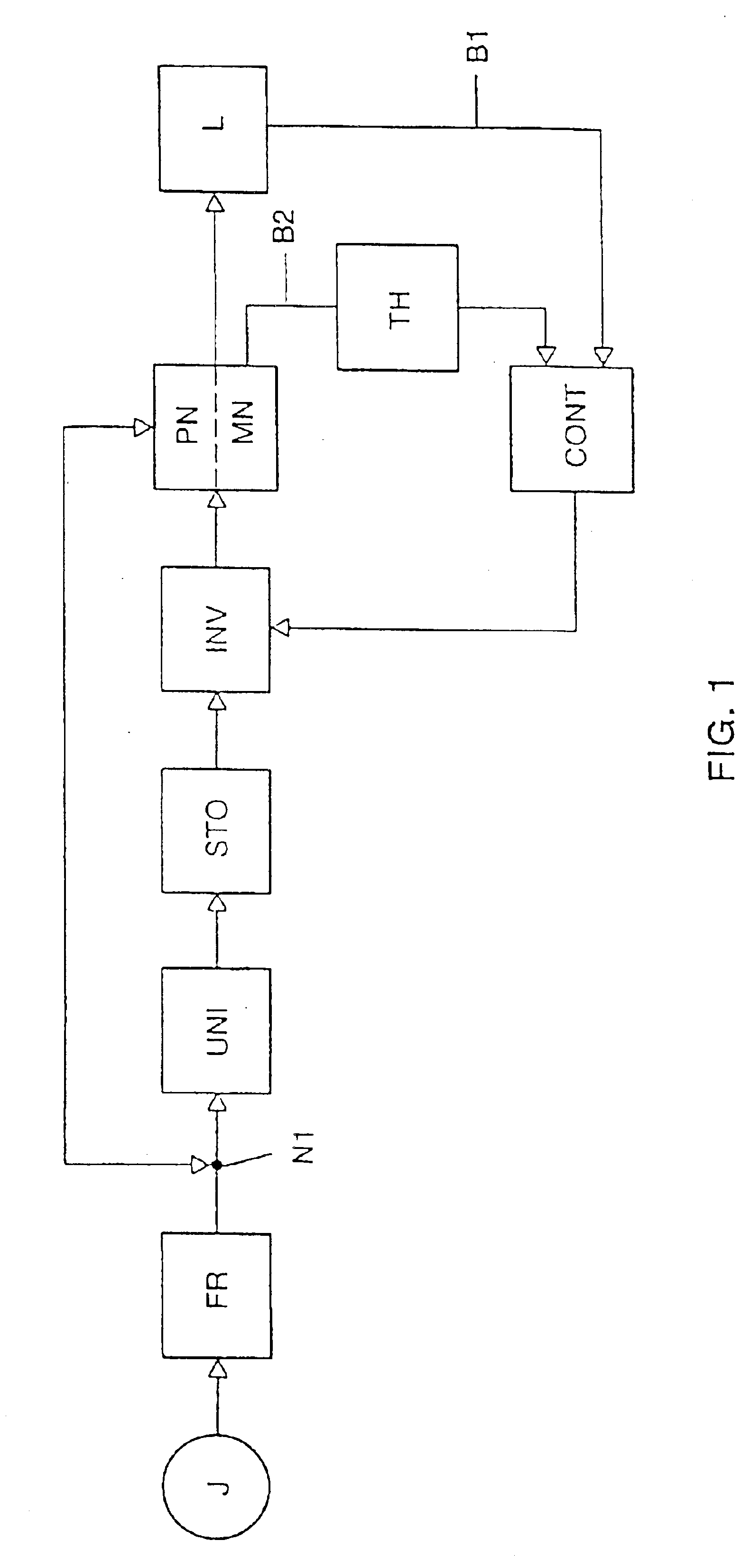
[0040]Represented in FIG. 1 is a block diagram for a circuit arrangement according to the invention for starting and operating discharge lamps. At connection terminals J, a line voltage from a line voltage source can be fed to the circuit arrangement. The line voltage is initially fed into a block FR. On the one hand, this block includes known means for filtering disturbances. On the other hand, this block includes a rectifier, which rectifiers the line voltage, which is an AC voltage. Usually, a bridge-connected full-wave rectifier is used for this purpose. Important for the function of a charge pump realized in the circuit arrangement is the property of the rectifier that it does not permit any current that allows an energy flow from the circuit arrangement to the line voltage source.

[0041]The rectified line voltage is fed to an electronic pumping switch UNI, a pumping node N1 being produced at the connecting point between the rectifier FR and the electronic pumping switch UNI. In...


PUM


Abstract

In the case of circuit arrangements for operating discharge lamps (Lp1, Lp2) which include a charge pump for reducing line current harmonics, an energy imbalance occurs when the lamps are started. In order for this not to lead to components being destroyed, but for sufficient ignition voltage nevertheless to be generated at the lamps (Lp1, Lp2), a threshold switch (MOV, TH) monitors the frequency of an inverter included in the circuit arrangement.

Description

FIELD OF THE INVENTION[0001]The invention relates to circuit arrangements for operating discharge lamps. In particular so-called charge pumps for reducing line current harmonics are applied.BACKGROUND OF THE INVENTION[0002]Circuit arrangements for starting and operating discharge lamps are used in electronic operating devices for discharge lamps. The starting of the discharge lamp is understood hereafter as meaning at least the ignition during an igniting phase. However, this may also be preceded by a preheating of electrode filaments during a preheating phase of the igniting phase. If the operating devices are operated on a line voltage, they have to conform to relevant regulations with respect to line current harmonics, for example IEC 1000-3-2. To ensure compliance with these regulations, circuit measures are necessary for reducing line current harmonics. Such a measure is the installation of so-called charge pumps. The advantage of charge pumps is the low level of circuit comple...

Claims


Application Information

Patent Timeline
Patent Type & Authority Patents(United States)
IPC IPC(8): H05B41/295H05B41/28H05B41/282
CPCH05B41/28H05B41/295Y10S315/07Y10S315/05H05B41/282
Inventor RUDOLPH, BERND
Owner PATENT TREUHAND GESELLSCHAFT FUR ELECTRIC GLUEHLAMPEN MBH
Why Eureka
Try Eureka