Trimming method and trimming device for a PLL circuit for two-point modulation

a trimming device and pll circuit technology, applied in the direction of modulation, pulse automatic control, transmission, etc., can solve problems such as pll control errors, and achieve the effect of keeping circuit complexity down and high level of practicability of inventive trimming methods

Inactive Publication Date: 2005-08-23
APPLE INC
View PDF14 Cites 43 Cited by
  • Summary
  • Abstract
  • Description
  • Claims
  • Application Information

AI Technical Summary

Benefits of technology

[0014]With this type of trimming, the output signal produced by the PLL circuit is not demodulated, because trimming involves reverting to the signal that is characteristic of the control error in the PLL circuit. Accordingly, it is not necessary to provide an internal or external demodulator, which keeps down circuit complexity and achieves a high level of practicability for the inventive trimming method.

Problems solved by technology

Provided that these signals do not have identical amplitudes (in this case, the modulation swings would already have been trimmed), this results in a PLL control error.
With this type of trimming, the output signal produced by the PLL circuit is not demodulated, because trimming involves reverting to the signal that is characteristic of the control error in the PLL circuit.

Method used


Image

  • Trimming method and trimming device for a PLL circuit for two-point modulation
  • Trimming method and trimming device for a PLL circuit for two-point modulation
  • Trimming method and trimming device for a PLL circuit for two-point modulation

Examples


Embodiment Construction

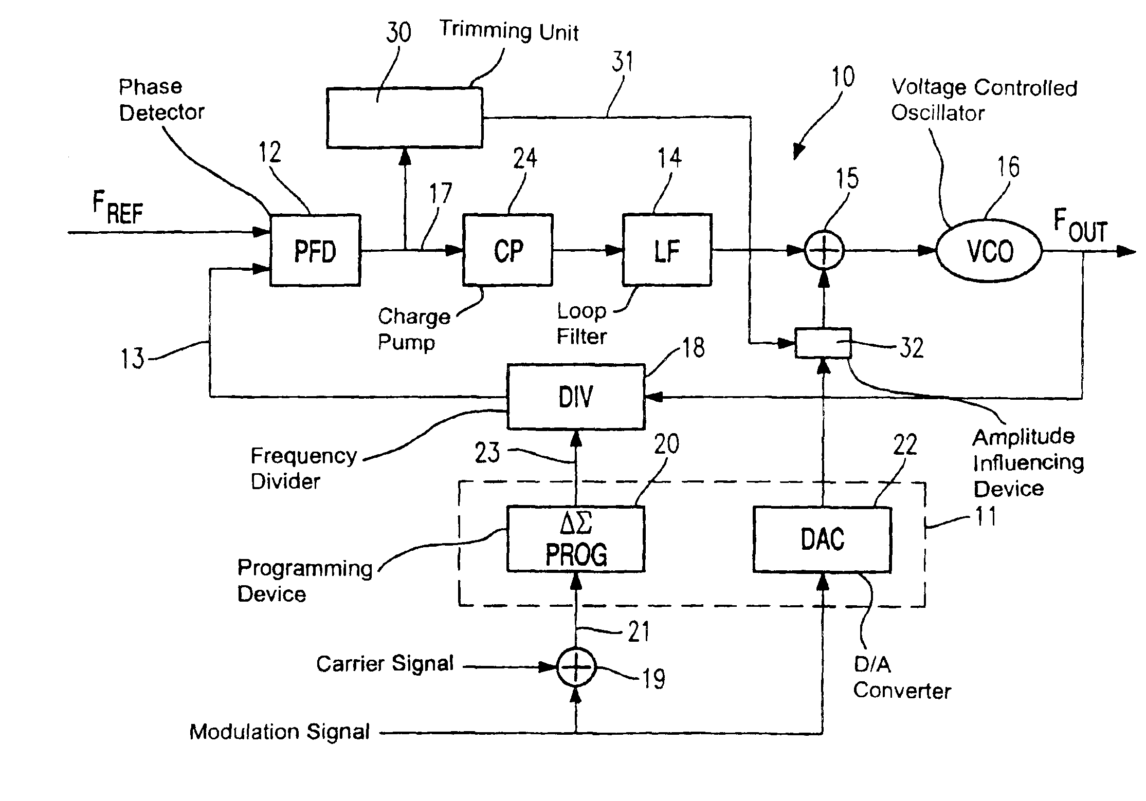
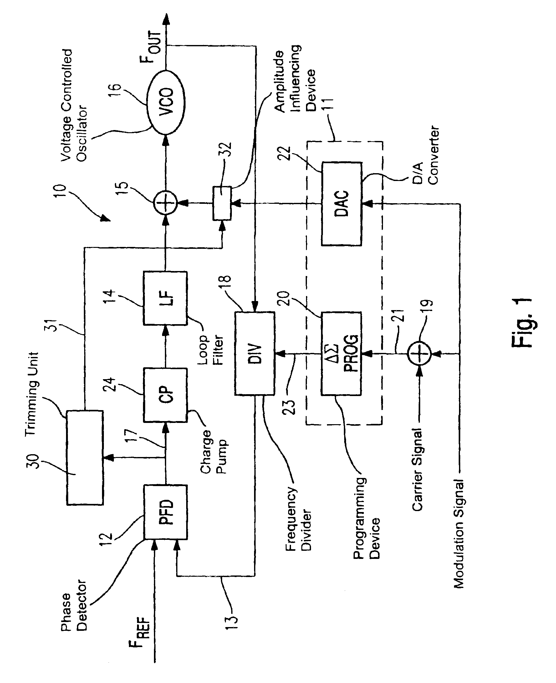
[0030]Referring now to the figures of the drawing in detail and first, particularly, to FIG. 1 thereof, there is shown a PLL circuit 10 which operates on the basis of the principle of two-point modulation and is coupled to a trimming unit 30.

[0031]In line with an ordinary design, the signal path of the PLL circuit 10 has a phase detector PFD (Phase Frequency Detector) 12, a charge pump CP 24, a loop filter LF 14, a summation point 15 and a voltage-controlled oscillator VCO 16.

[0032]The VCO 16 is the element that produces oscillations in the PLL circuit 10 and delivers a signal of frequency FOUT as the output signal from the PLL circuit 10.

[0033]The PLL control loop 10 is closed by a feedback path that returns the output signal from the VCO 16 to the frequency detector 12 via a programmable frequency divider DIV 18.

[0034]The action of the PLL circuit as a frequency synthesizer for two-point modulation is known. Two-point modulation involves impressing a digital and an analog modulati...


PUM


Abstract

In the case of a trimming method for a PLL circuit operating based on the principle of a two-point modulation, the PLL circuit is locked without any modulation being impressed and then an analog and a digital modulation signal are impressed into the locked PLL circuit. A signal that is characteristic of the PLL control error is tapped from the PLL circuit, and the modulation swing in the analog modulation signal is changed such that the characteristic signal has the same value as before the analog and digital modulation signals were impressed.

Description

CROSS-REFERENCE TO RELATED APPLICATION[0001]This application is a continuation of copending International Application No. PCT / DE02 / 00727, filed Feb. 20, 2002, which designated the United States and was not published in English.BACKGROUND OF THE INVENTIONField of the Invention[0002]The invention relates to a trimming method for a PLL (Phase Locked Loop) circuit operating on the basis of the principle of two-point modulation and also to such a PLL circuit designed for impressing an analog and a digital modulation signal.[0003]A low-complexity implementation of a transmitter design for transceivers in mobile radio systems is provided by transmitters in which a PLL circuit is used as a frequency synthesizer and is used to provide frequency modulation and phase modulation for a radio frequency signal.[0004]The modulation signal is normally impressed into the PLL circuit using a frequency divider arranged in the PL loop's feedback path. This involves using a digital modulation signal for ...

Claims


Application Information

Patent Timeline
Patent Type & Authority Patents(United States)
IPC IPC(8): H03C3/00H03L7/08H03L7/089H03C3/09H03L7/197H03L7/16
CPCH03C3/0925H03C3/0933H03C3/0941H03C3/095H03L7/0893H03L7/1976
Inventor HAMMES, MARKUSVAN WAASEN, STEFAN
Owner APPLE INC
Why Eureka
Try Eureka