Optical switching apparatus and optical communication network system

a technology of optical communication network and optical switching apparatus, applied in multiplex communication, transmission monitoring, instruments, etc., can solve the problems of several milliseconds, momentary power failure, slow switching speed, etc., and achieve the effect of preventing the notification of an erroneous alarm and high reliability

Inactive Publication Date: 2005-08-23
HITACHI LTD
View PDF7 Cites 18 Cited by
  • Summary
  • Abstract
  • Description
  • Claims
  • Application Information

AI Technical Summary

Benefits of technology

[0010]An object of the present invention is to provide a highly reliable optical communication network system for switching routes without any conversion of an optical signal, which is preventing notification of an erroneous alarm during switching by an optical switch.

Problems solved by technology

However, in the OXC and the OADM directly processing the optical signal, there occurs a problem, in the case of the most often used mechanical optical switch, that a switching speed is slow, which is several milli-seconds at the shortest, while a transmission rate of the optical signal to be passed is 10 Gbps or higher (e.g., 40 Gbps), which is much higher than that of an electric signal.
Consequently, if switching of signal routes similar to the conventional apparatus for processing an electric signal is simply executed for the OXC or the OADM, a momentary power failure occurs, where an optical signal of several million bits, that is, several tens of frames, is lost because of its inability to pass through the optical switch during optical signal route switching by the optical switch.
In the apparatus provided with the above-described trouble monitoring function, depending on an installing position of a monitoring circuit or a monitoring method, a momentary power failure due to route switching by the optical switch may be detected as an optical signal power failure, BER degradation or stepping-out of synchronization.
Thus, unless monitoring is carried out by considering time necessary for route switching by the optical switch or an operation time of the above-described trouble monitoring function, even if the switching has been normally carried out, a situation may occur where an alarm is given to the downstream side of the optical signal advancing direction or the apparatus for monitoring and controlling troubles.
Consequently, an operation of the entire OXC or OADM, or an operation of a communication system (network) using the OXC or the OADM becomes unstable, it brings about a state when the RAS function can not be operated as desired.
However, such a method is not preferable for an improvement of the RAS function because an original alarm monitoring ability is reduced.
However, the masking function by the software in the conventional communication apparatus for processing an electric signal cannot simply be applied to the OXC or the OADM.
However, recovery from the optical signal power failure is detected during switching time (about 1 milli-sec.) after completion of switching.
Consequently, when correct operation of route switching is carried out by distinguishing a momentary power failure due to switching of the optical switch from a disconnection of an optical fiber as a fixed trouble, if only the conventional trouble detection method or the conventional masking function by the software simply is applied to the OXC or the OADM, the RAS function becomes short.

Method used


Image

  • Optical switching apparatus and optical communication network system
  • Optical switching apparatus and optical communication network system
  • Optical switching apparatus and optical communication network system

Examples


Embodiment Construction

[0031]Next, description will be made for an optical communication network system according to an embodiment of the present invention.

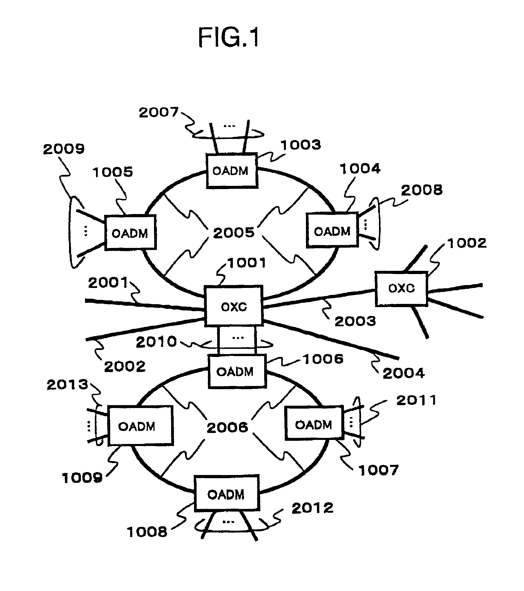
[0032]As shown in FIG. 1, an optical communication network system of this embodiment includes optical add-drop multiplexing apparatuses (OADM) 1003 to 1009 and optical cross-connect apparatuses (OXC) 1001 and 1002, which are connected through optical fibers 2001 to 2006. Specifically, the optical add-drop multiplexing apparatuses (OADM) 1003 to 1005 are connected in a ring shape through the optical fiber 2005, and optical add-drop multiplexing apparatuses (OADM) 1006 to 1009 are connected in a ring shape through the optical fiber 2006. The optical fiber 2005 and the optical fibers 2001 to 2004 are connected by the optical cross-connect apparatus (OXC) 1001. The optical cross-connect apparatus (OXC) 1001 is also connected to the optical add-drop multiplexing apparatus (OADM) 1006. The optical fiber 2003 also are connected to other optical fibers through...


PUM


Abstract

An optical communication network system is disclosed, which includes an optical switching apparatus. The optical switching apparatus includes an optical switch for switching and setting routes of an optical signal without being converted, a control unit for instructing the optical switch to execute a route switching operation, and a performance monitor for detecting performance of the optical signal having a route set by the optical switch. The performance monitor issues an alarm when the performance detected is deteriorated from predetermined performance. The control unit includes an alarm masking unit for masking the alarm issued from the performance monitor at least for a predetermined masking period from a starting time of a switching operation by the optical switch, and thus preventing the alarm from being issued.

Description

BACKGROUND OF THE INVENTION[0001]The present invention relates to an optical communication network system, and more particularly to an optical communication network system for performing switching of routes of an optical signal without converting the optical signal into an electric signal.[0002]In order to deal with a rapid increase in data traffic represented by the Internet and a sudden increase in demand for multimedia communications including images, audio and data, a higher speed operation and a larger capacity operation have been pushed ahead for a transmission line and a communication node, which constitute a communication network, and there have been progresses made in the introduction of an optical communication apparatus using an optical fiber and an optical signal. In addition, in place of a conventional communication apparatus for processing an optical signal, in which the optical signal is converted into an electric signal once, studies have been conducted on practical ...

Claims


Application Information

Patent Timeline
Patent Type & Authority Patents(United States)
IPC IPC(8): H04B10/08H04Q11/00H04J14/02H04B10/27H04B10/03H04B10/077H04B10/079H04B10/275H04B10/291H04Q3/52
CPCH04B10/0793H04B10/0795H04J14/0283H04J14/0286H04Q11/0005H04J14/0241H04J14/0246H04J14/0227H04J14/0282H04Q2011/0073H04Q2011/0081H04Q2011/0083
Inventor KITAJIMA, SHIGEKIKAKIZAKI, SUNAOTSUSHIMA, HIDEAKIFUKASHIRO, YASUYUKI
Owner HITACHI LTD
Why Eureka
Try Eureka