

Frequency-controlled load driver for an electromechanical system
a technology of electromechanical system and load driver, which is applied in the direction of electromagnetic relay, relay, electric apparatus, etc., can solve the problems of affecting the operation of precision systems, affecting the transitional response of electromechanical systems, and affecting the operation of electrically operated hydraulic valves,
- Summary
- Abstract
- Description
- Claims
- Application Information
AI Technical Summary
Benefits of technology
Problems solved by technology
Method used
Image

Examples
Embodiment Construction
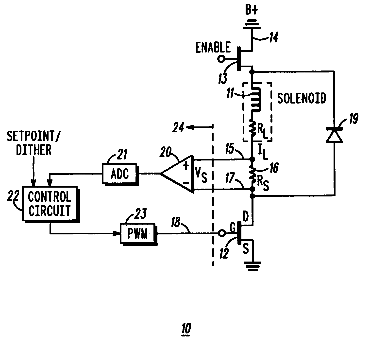
[0013]The present invention provides a frequency-controlled load driver current for an electromechanical system, such as a valve actuator for example. A fast transient response scheme for current control with separate control modes for steady state and transient conditions is also provided. The present invention also allows a simple change in the frequency of operation over a range of operation of the electromechanical system.
[0014]Referring to FIG. 1, a load driver circuit 10 is illustrated in which the load current IL through a desired load, comprising an inductive solenoid coil 11 (with internal resistance RL), is controlled by a driver device 12, comprising an FET transistor for example, connected in series with the solenoid coil 11. One end of the solenoid coil 11 is coupled to a power supply terminal 14 at which a voltage potential B+ is provided. The other end of the solenoid coil 11 is connected to a positive sense terminal 15. A sensing resistor RS 16 is provided between th...
PUM
 Abstract
Description
Claims
Application Information