
Wave image compression

Inactive Publication Date: 2005-08-23
TRIDENT SYST
View PDF13 Cites 16 Cited by
  • Summary
  • Abstract
  • Description
  • Claims
  • Application Information

AI Technical Summary

Benefits of technology

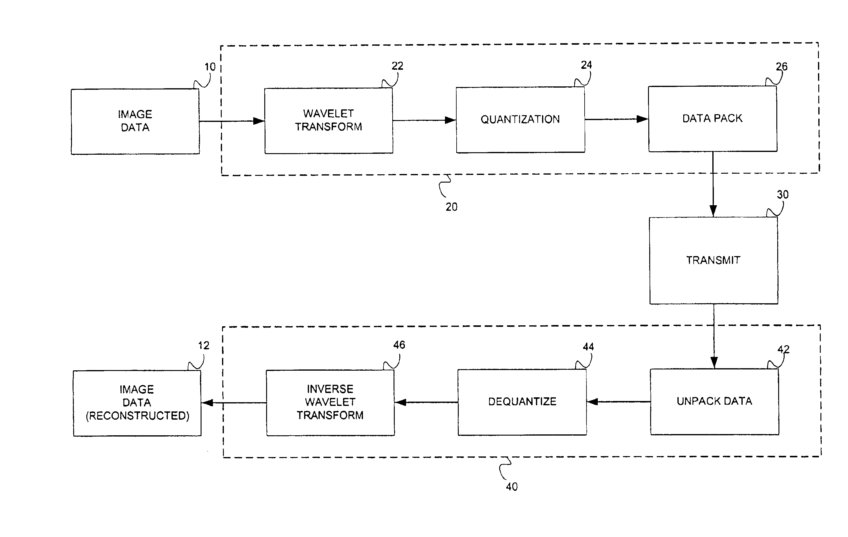
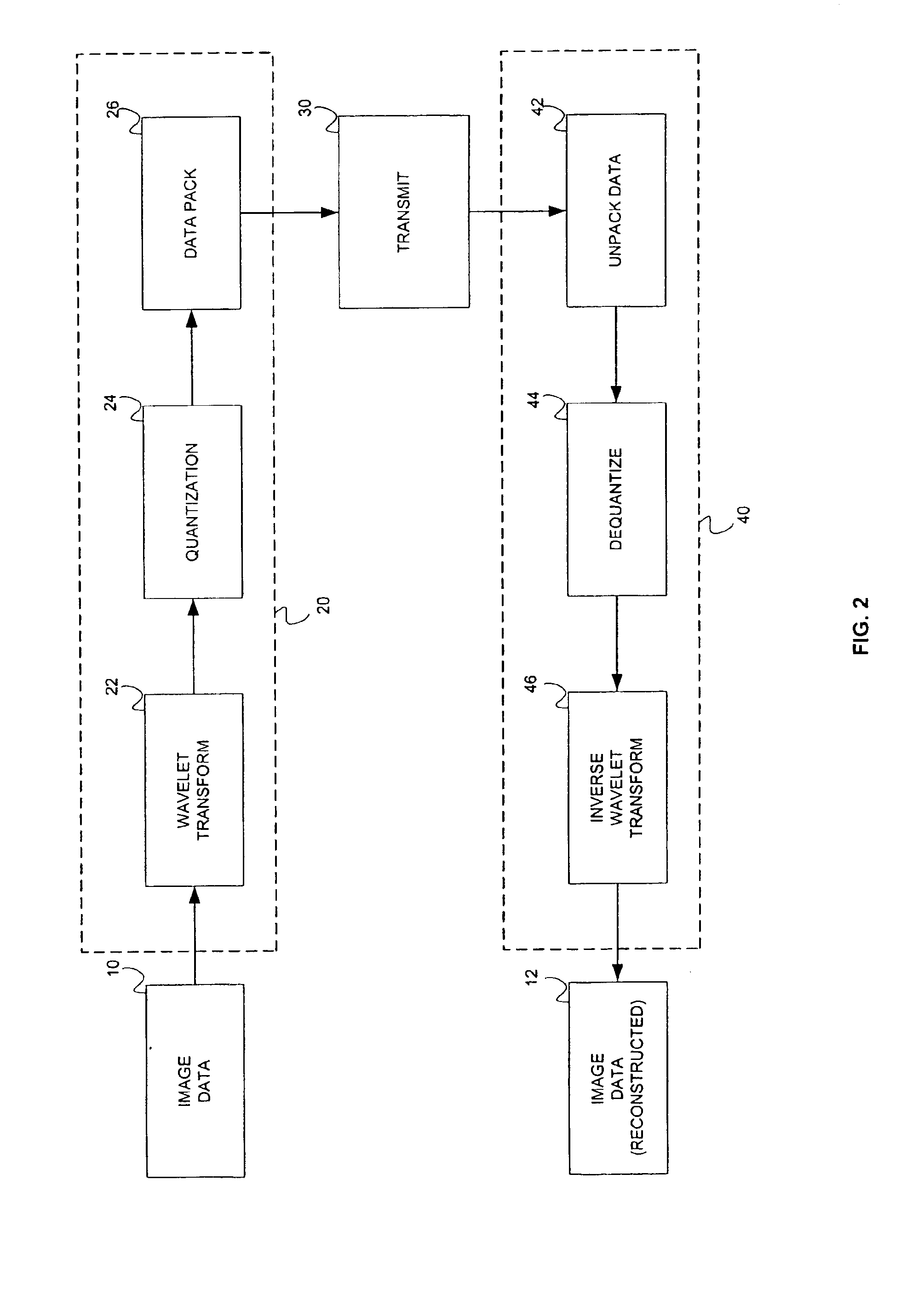
[0011]In a first embodiment of the present invention, a method of image compression, comprises the steps of recursively transforming an image using a Discrete Wavelet Transform. This creates a plurality of levels including at least a first level, multiple intermediate levels, and a low-low pass subband of the last level. The transformed image at each level is quantized, and datapacking the quantized image is performed. The step of datapacking further includes, encoding of the first level using adaptive run length coding of zero coefficients combined with Huffman codes; encoding of the intermediate levels using run-length coding of zero coefficients and a predetermined two-knob huffman table for non-zero coefficients and encoding of the low-low pass subband using a

Problems solved by technology

Unfortunately, high image quality creates a demand for increased storage space for digital data.
In the cases where the signal is defined as an image, the problem of compression is to minimize the number of bits needed to digitally represent the image.
Without compression, most digital information and transmission through the normal limited bandwidth channels is difficult or infeasible for practical use.
Lossy compression further reduces the amount of needed memory, but does not guarantee exact restoration of the original data.
Existing technology for lossless compression, however, may not allow for high compression ratios.
Although JPEG is popular, one known problem is that, as the compression level increases, the image quality worsens and distortion grows in these blocks individually.
This problem leads to a block effect that introduces edges into the image, which is normally detected as jagged edges or maybe a blurring to the observer of the decompressed image.

Method used


Image

  • Wave image compression
  • Wave image compression
  • Wave image compression

Examples


Embodiment Construction

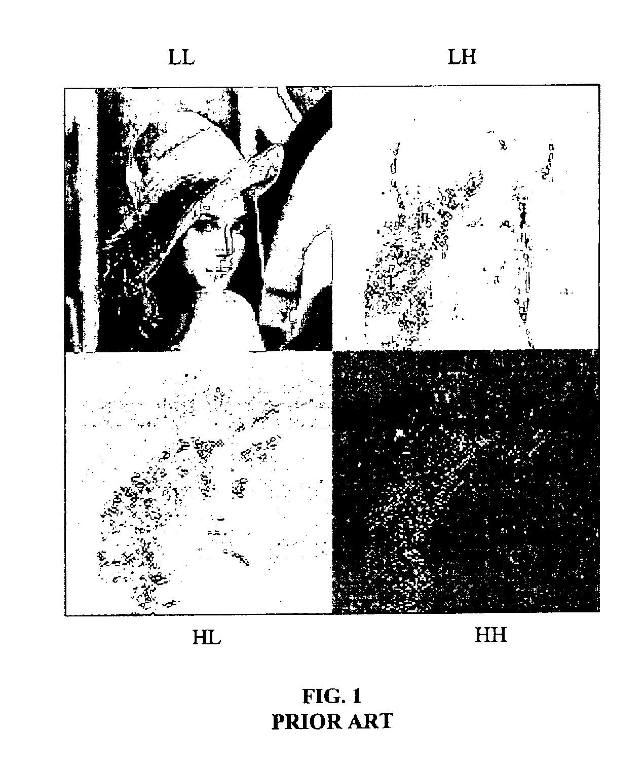
[0035]There is shown in FIGS. 1-16 an illustration of an embodiment of the present invention, a method and apparatus for processing a image data.

[0036]Referring to FIG. 2, the method of the embodiment uses three steps for the encoder of image compression 20—forward wavelet transform 22, quantization 24, and data packing 26. Each of the steps will be described in detail herein.

[0037]In a first embodiment of the invention, digital image data 10 having pixel values is provided to a wavelet transform process 22. Wavelet transform process 22 uses a multiple level wavelet transform, utilizing symmetric biorthogonal seven and nine tap filters. Decimation and interpolation procedures are incorporated in the wavelet transform. This allows the forward and inverse transform to be done with about half the number of multiply adds. Also, the image is mirrored at the edges before transformation, providing better image reconstruction from the quantized wavelet coefficients. Wavelet data is the outp...


PUM


Abstract

A method of image compression comprises the steps of recursively transforming a image using a Discrete Wavelet Transform. This creates a plurality of levels including at least a first level, multiple intermediate levels, and a low-low pass subband of the last level. The transformed image at each level is quantized, and datapacking the quantized image is performed. The step of datapacking further includes, encoding of the first level using adaptive run length of zero cofficients; encoding of the intermediate levels using run-length coding of zero coefficients and a predetermined two-knob huffman table for non-zero coefficients and encoding of the low-low pass subband using a low frequency packing algorithm.

Description

CROSS REFERENCE TO RELATED APPLICATIONS[0001]This application claims the benefit of U.S. Provisional Application Ser. No. 60 / 171,509, filed on Dec. 22, 1999.FEDERALLY SPONSORED RESEARCH AND DEVELOPMENT[0002]This invention was made in part with government support under contract no. DAAB07-97-D-H754 awarded by the U.S. Army. The U.S. Government has certain rights in this invention.TECHNICAL FIELD OF THE INVENTION[0003]The present invention relates to the field of digital data compression and decompression in particular to a compression and decompression method that implements combined discrete wavelet transformation, and a method of data packing.BACKGROUND OF THE INVENTION[0004]The use of digitized multimedia, such as motion video and still images, has increased the demand on microprocessors and available bandwidth. The use of World Wide Web browsers as graphical user interfaces and electronic commerce on the Internet has increased the need for graphical images that are visually appea...

Claims


Application Information

Patent Timeline
IPC IPC(8): G06K9/36H04N7/26
CPCH04N19/63H04N19/61H04N19/12H04N19/1883H04N19/13
Inventor HSU, CHARLES C.TAMBURELLO, PHILIP M.
Owner TRIDENT SYST
Learn More