Optical waveguiding apparatus having reduced crossover losses
- Summary
- Abstract
- Description
- Claims
- Application Information
AI Technical Summary
Benefits of technology
Problems solved by technology
Method used
Image

Examples
Embodiment Construction
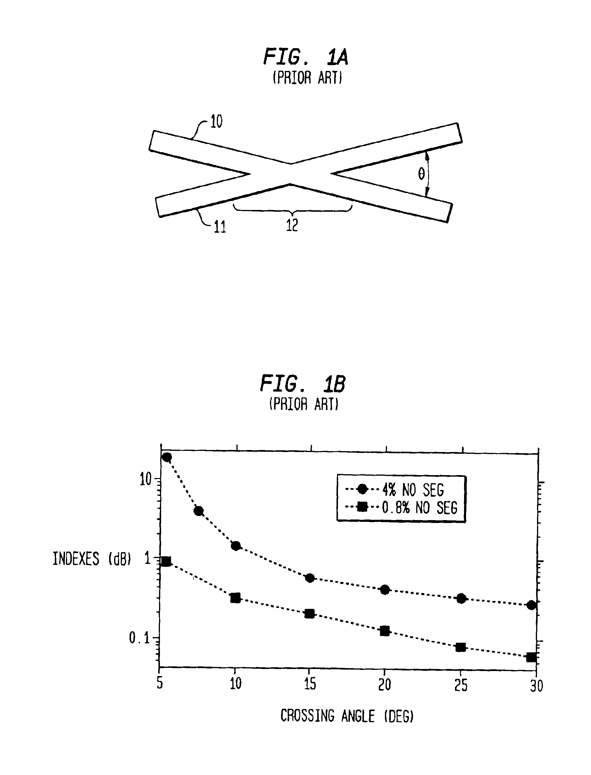
[0020]Referring to the drawings, FIGS. 1A and 1B, which are conventional, were described in the Background of the Invention.
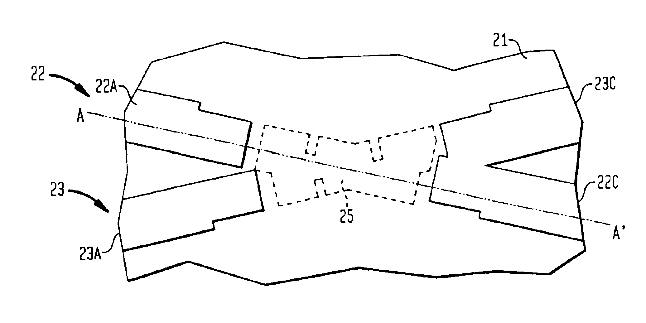
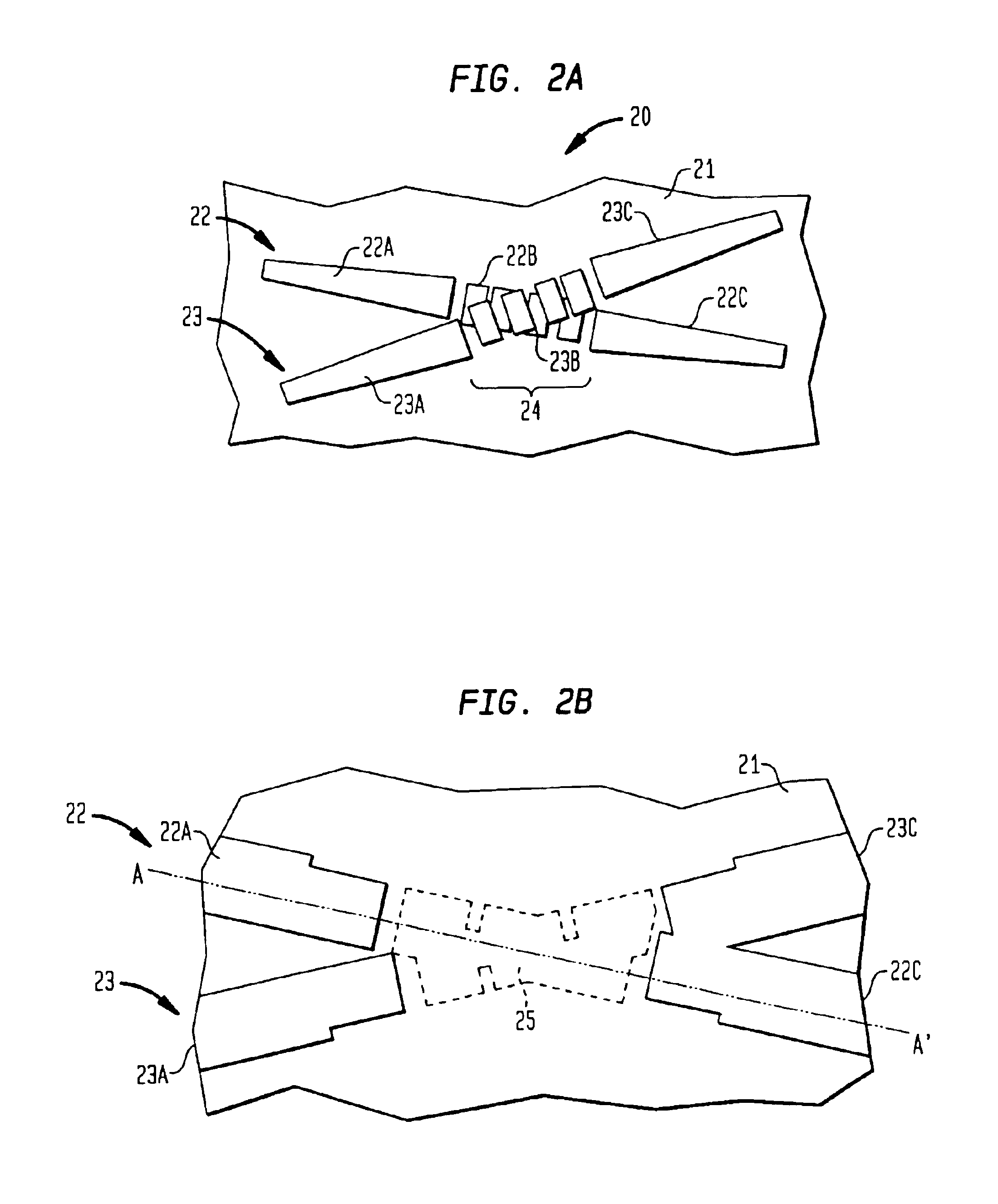
[0021]FIG. 2A, which is useful in designing a waveguide crossover in accordance with the invention, illustrates an optical waveguide apparatus 20 comprising an exemplary waveguide crossover region 21. In essence, the crossover region 21 comprises a pair of co-planar optical waveguides 22 and 23 intersecting at an angle Ø. Each optical waveguide 22, 23 comprises a core section including a plurality of segments 22B, 23B which the waveguides share across an intersection region 24. Advantageously each waveguide 22, 23 is adiabatically tapered to enlarged width at the intersection region and adiabatically tapered to reduced width leading out of the region. Waveguide 22, for example provides a path comprising continuous tapered input core section 22A of expanding width leading into the intersection region 24, the plurality of segments 22B in the region 24, and a cont...
PUM
 Abstract
Description
Claims
Application Information
 - Generate Ideas
- Intellectual Property
- Life Sciences
- Materials
- Tech Scout
- Unparalleled Data Quality
- Higher Quality Content
- 60% Fewer Hallucinations
Browse by: Latest US Patents, China's latest patents, Technical Efficacy Thesaurus, Application Domain, Technology Topic, Popular Technical Reports.
© 2025 PatSnap. All rights reserved.Legal|Privacy policy|Modern Slavery Act Transparency Statement|Sitemap|About US| Contact US: help@patsnap.com