Communication device

a communication device and antenna directivity technology, applied in the field of communication devices, can solve the problems of circuit components not operating, the detection of the mobile station in the 45-degree direction cannot be relied on from the start, and the actual inability to impart high antenna directivity, so as to improve the reception quality of the communication signal, reduce interference, and raise calibration efficiency

Inactive Publication Date: 2005-08-23
KOKUSA ELECTRIC CO LTD
View PDF1 Cites 135 Cited by
  • Summary
  • Abstract
  • Description
  • Claims
  • Application Information

AI Technical Summary

Benefits of technology

[0042]Since calibration is therefore performed by not using a signal that is transmitted / received by the communication device or the like but by using the calibration signal, the calibration accuracy can be enhanced. Moreover, as the processing is effected on the received signal after the received signal has been diminished by the cancellation signal corresponding to the received calibration signal, the reception quality of communication signals is improved.
[0052]The provision of a dedicated antenna for transmitting the calibration signal raises the calibration efficiency.
[0053]The calibration signal transmitting antenna is preferably located within a short distance from the communication antenna. When the calibration signal transmitting antenna is located within a short distance from the communication antenna, the power of the calibration signal which is transmitted by the calibration signal transmitting antenna can be reduced so as to reduce the interference that the calibration signal imparts to the communication signal. This improves the reception quality of the communication signal.
[0058]Therefore, since a frequency signal that is generated by a common signal generator performs frequency conversion of signals which are supplied to multiple antenna chains, unlike the case of using different signal generators for the individual antenna chains, for example, no phase shift arises in the frequency signal between the antenna chains. This improves the calibration accuracy.
[0063]Compared with the case where this processing (detection) is performed constantly, this configuration shortens the time period during which the calibration signal is contained in the received signal to thereby improve the reception quality of communications signals. Moreover, by also shortening the time period for transmitting the calibration signal, this configuration further improves the transmission quality of communication signals which are transmitted to other parties.

Problems solved by technology

If the transmitter section has not been calibrated, however, it is actually impossible to impart high antenna directivity in the 45-degree direction because phase differences and level differences (amplitude differences) are present in the individual antenna chains.
Moreover, if the receiver section has not been calibrated, the detection of the mobile station in the 45-degree direction cannot be relied on from the start.
These circuit components do not operate when calibration is not an objective.
However, in a conventional CDMA base station that conducts calibration, such as that shown in FIG. 6, the fact that transmission is conducted at high power during system operation makes it difficult to secure an adequate dynamic range in the calibration circuits which are provided in the transceiver units M1-Mn, particularly in the mixer 71.
Moreover, the conventional CDMA base station also has other problems, such as that the attenuator 72 has to be controlled according to the system state and that the transceiver units M1-Mn are structurally complex.
However, as mentioned above, since the large transmission power occurring during system operation makes it difficult to secure an adequate dynamic range, detection of the exact value and removal would become extremely difficult during operation.
Moreover, since the number of transceiver units depends on the n number of antennas making up the adaptive array antenna, the transceiver unit configuration would become complex and greatly increase equipment cost.
Furthermore, the transceiver units cannot readily be miniaturized or decreased in cost by large scale integration (LSI) or like technologies because they are analog units.

Method used


Image

  • Communication device
  • Communication device
  • Communication device

Examples


first embodiment

[0072

[0073]A CDMA base station according to a first embodiment of the present invention will now be explained with reference to the drawings.

[0074]The processing when using a communication antenna to receive and transmit communication signals in the first embodiment is similar to what was explained earlier with reference to FIG. 6 regarding the prior art. In the following, therefore, only the points that characterize the CDMA base station of this embodiment will be explained in detail and points similar to those set out with reference to the prior art example of FIG. 6 will be omitted or discussed only briefly.

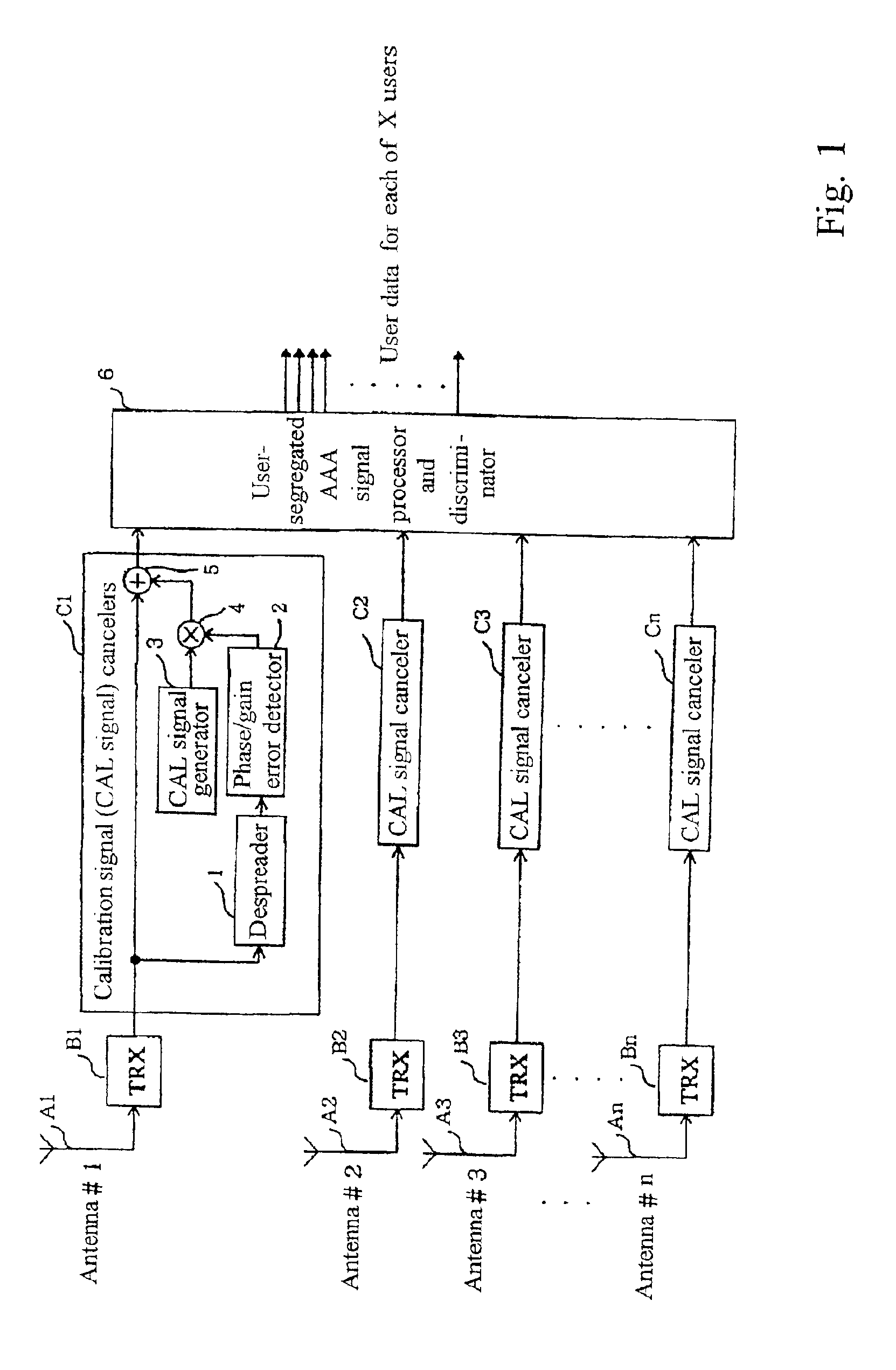
[0075]FIG. 1 shows the configuration of the CDMA base station of the first embodiment. The CDMA base station comprises n number of communication (transmission / reception) antennas A1-An constituting an adaptive array antenna, n number of transceiver units (TRX) B1-Bn, and n number of calibration signal (CAL signal) cancellers C1-Cn. The communication antennas A1-An, transceiver...

second embodiment

[0118

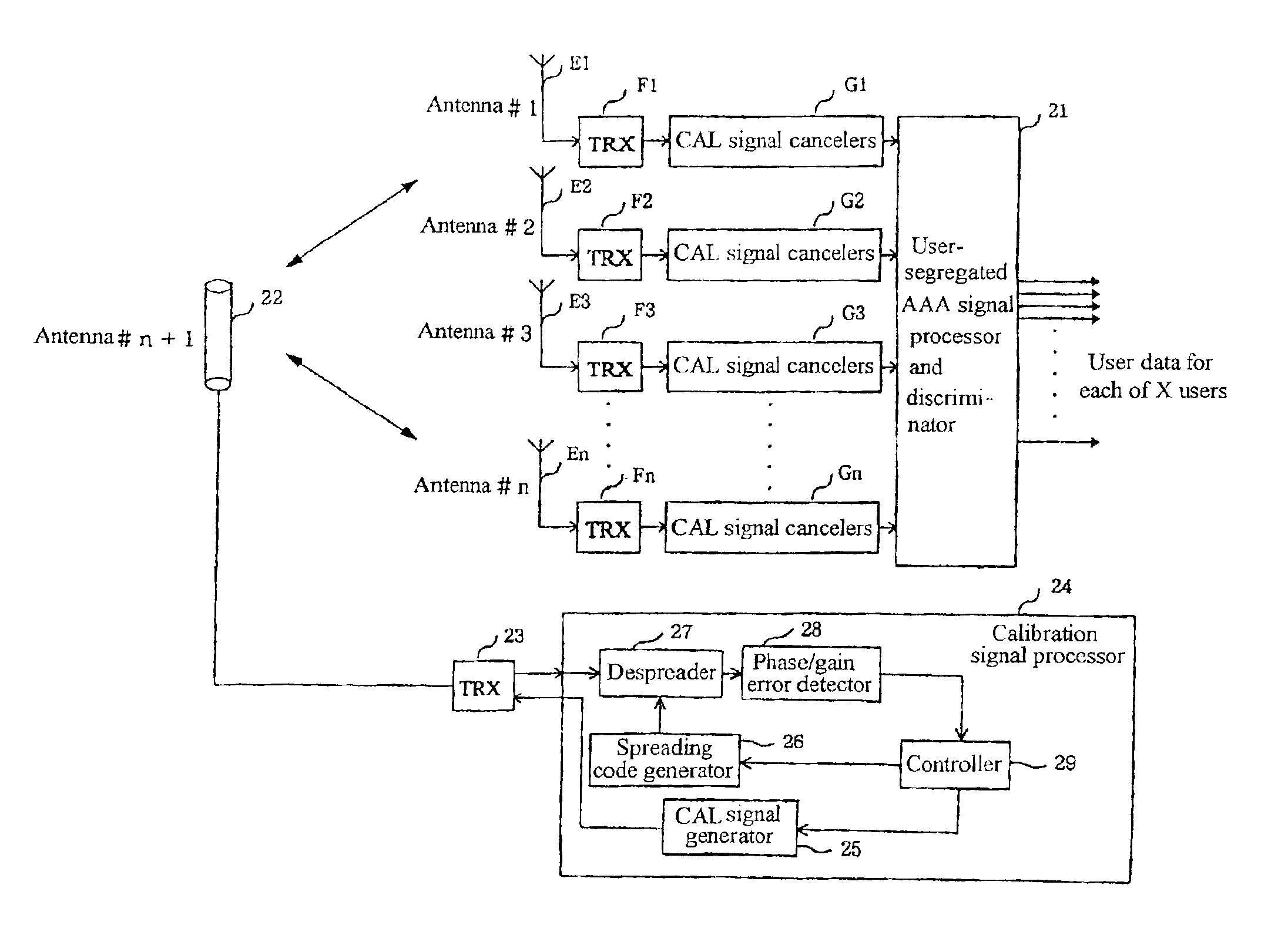
[0119]A CDMA base station according to a second embodiment of the present invention will now be explained with reference to FIG. 3.

[0120]FIG. 3 shows the configuration of the CDMA base station of the second embodiment. The second embodiment differs from the first embodiment of FIG. 1 in that, for example, it is provided with calibration signal transmitting capability. Constituent elements similar to those of the first embodiment include n number of communication (transmit / receive) antennas E1-En constituting an adaptive array antenna, D number of transceiver units (TRX) F1-Fn, n number of calibration signal (CAL signal) cancellers G1-Gn. Similar to the first embodiment, the communication antennas E1-EN, transceiver units F1-FN and CAL signal cancellers G1-GN are combined in sets so as to form n number of communication antenna chains. The CDMA base station of the second embodiment is also equipped with a user-segregated AAA signal processor and discriminator 21 which is common t...

third embodiment

[0152

[0153]A CDMA base station according to a third embodiment of the present invention will now be explained with reference to FIG. 4.

[0154]The explanation of the third embodiment will be extended to include configurational details of the transceiver units of the communication antenna chains discussed regarding the first and second embodiments and configurational details of the CAL signal transceiver unit of the second embodiment. For simplicity of description, the third embodiment will be explained with reference to a configuration having an adaptive array antenna comprising four communication antennas H1-H4.

[0155]The configuration of the CDMA base station of the third embodiment is shown in FIG. 4. This CDMA base station is equipped with four communication (transmission and reception) antennas H1-H4 constituting an adaptive array antenna, four duplexers (DUP) I1-I4 that function to separate the transmission / reception chains by filtering, four receiver (RX) units J1-J4 and four tr...


PUM


Abstract

A communication device for transmitting and / or receiving signals by using a communication antenna includes signal characteristic information detection means for detecting information regarding signal characteristics of a calibration signal which are contained in a signal received by the communication antenna, calibration means for calibrating a communication antenna chain based on the detected signal characteristic information, and cancellation signal generating means for generating a cancellation signal corresponding to a calibration signal contained in the signal received by the communication antenna based on the calibration signal. The device also includes signal cancellation-by-subtraction means for subtracting the generated cancellation signal from the signal received by the communication antenna, and receive signal processing means for processing the received signal that is diminished by the cancellation signal.

Description

BACKGROUND OF THE INVENTION[0001]1. Field of the Invention[0002]The present invention relates to a communication device, typically a receiver, that conducts wireless communication by, for example, DS-CDMA (direct sequence-code division multiple access) using an adaptive array antenna, and more particularly, to a technology for improving calibration accuracy at the time of calibrating communication antenna chains and for improving the reception quality of received signals.[0003]2. Description of the Prior Art[0004]In recent years, consideration has been given to CDMA transceiver circuits that utilize adaptive array antennas (AAAs).[0005]When an adaptive array antenna is used to receive and transmit signals, its multiple antenna elements are individually weighted to control the directivity of the overall antenna. At the time of signal reception, for example, the adaptive array antenna is controlled so as to achieve maximum directivity in the direction of the desired incoming wave and ...

Claims


Application Information

Patent Timeline
Patent Type & Authority Patents(United States)
IPC IPC(8): H01Q3/26H04B1/707H04B7/04H04B7/08H04J13/00
CPCH01Q3/267H04B1/7107H04B7/04
Inventor MIYATANI, TETSUHIKO
Owner KOKUSA ELECTRIC CO LTD
Why Eureka
Try Eureka