
Methods for detecting, computing and disseminating location information associated with emergency 911 wireless transmissions

a wireless transmission and location information technology, applied in the field of radiotelephony and locating a radiotelephony device, can solve the problems of inability to determine the physical location of a radiotelephone, the inability to use a gps system in many applications, and the inability to know which antenna the radiotelephone is in communication with

Inactive Publication Date: 2005-08-23
TARSUS TRUST COMPANY LIMITED AS TRUSTEE FOR TARSUS CASUALTY & LIFE COMPANY A SECURED CREDITOR OF THE ASSIGNOR
View PDF10 Cites 19 Cited by
  • Summary
  • Abstract
  • Description
  • Claims
  • Application Information

AI Technical Summary

Benefits of technology

[0007]Other techniques based upon signal strength and trilaterialization have been employed, but they are generally effect

Problems solved by technology

It is not possible to determine the physical location of a radiotelephone, when the radiotelephone is capable of moving from one location to another.
Furthermore, the knowledge of which antenna the radiotelephone is in communication with does not form a basis for determining the location of the radiotelephone itself.
However, the employment of a GPS system is impractical in many applications.
Moreover, inclement weather conditions, terrain features, and buildings further restrict the ability of the GPS receiver to determine its position.
The GPS system also requires mobile devices to be equipped to link to earth satellites which makes these mobile devices more expensive.
However, these techniques are not effective in dense urban areas.
The multipath phenomenon renders most analytical location computational techniques such as time-of-arrival (TOA) or time-difference-of-arrival (TDOA) substantially useless in urban areas.

Method used


Image

  • Methods for detecting, computing and disseminating location information associated with emergency 911 wireless transmissions
  • Methods for detecting, computing and disseminating location information associated with emergency 911 wireless transmissions
  • Methods for detecting, computing and disseminating location information associated with emergency 911 wireless transmissions

Examples


Embodiment Construction

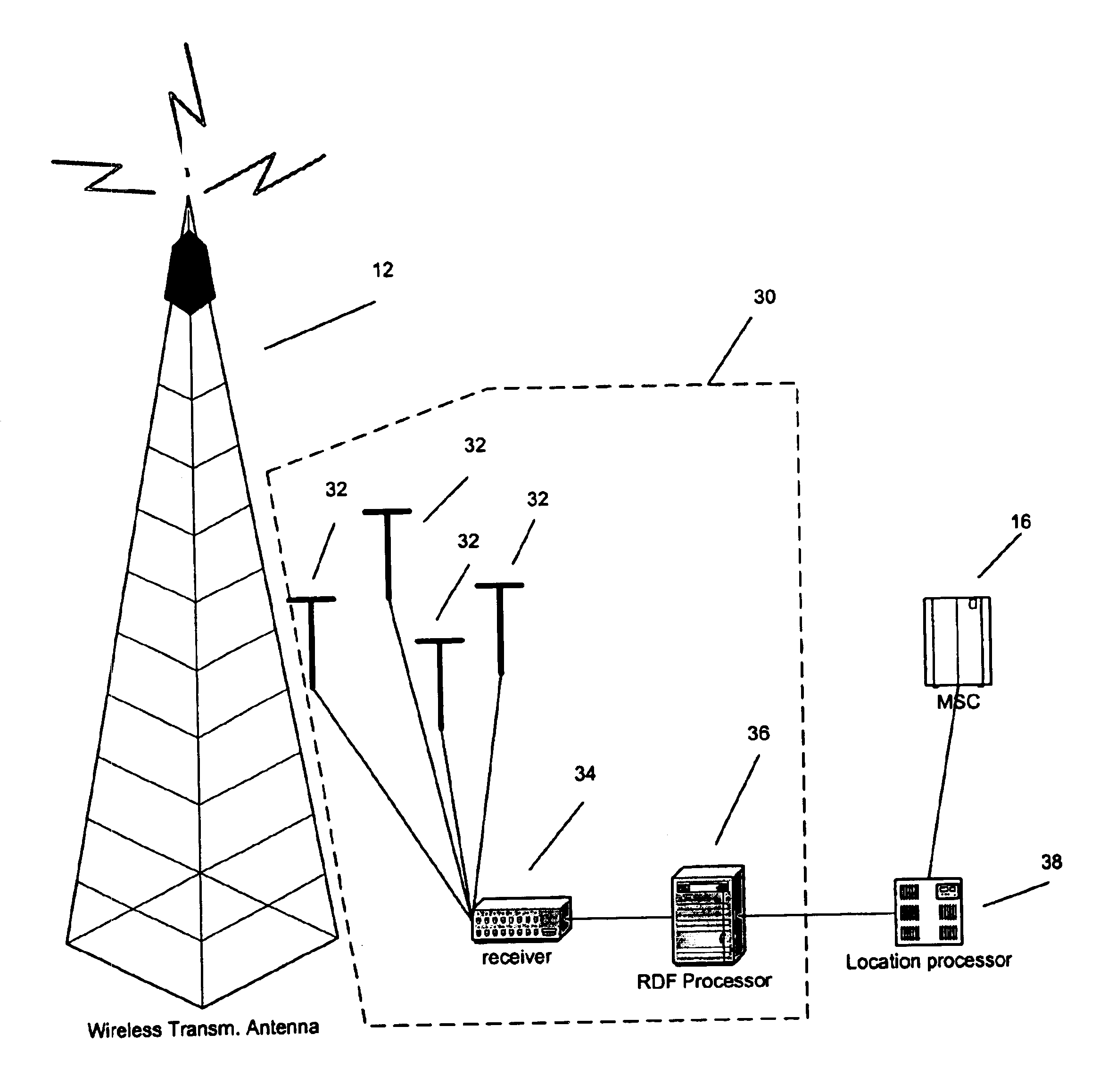
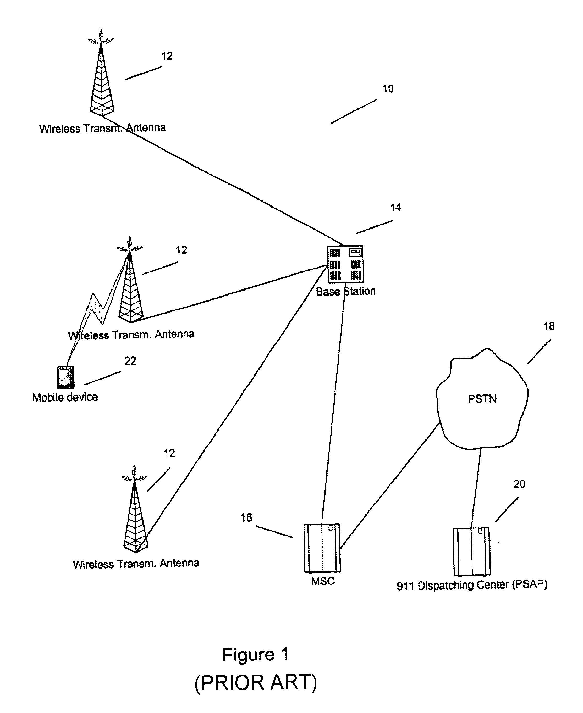
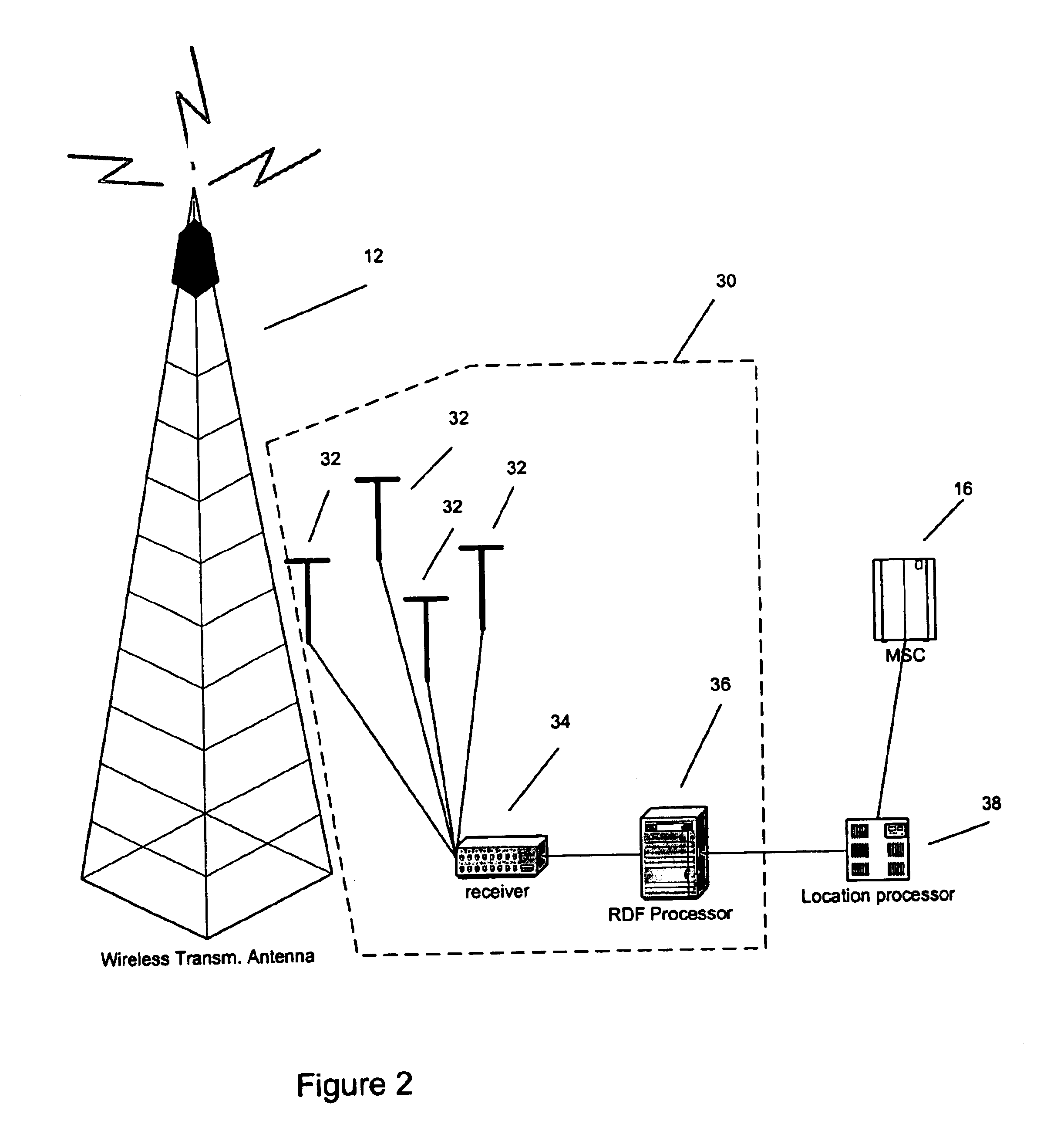
[0022]Referring now in greater detail to the drawings, in which like numerals represent like components throughout several views, FIG. 1 depicts architecture of a wireless communication network 10. The wireless communication network 10 has a plurality of communication antennas 12, also known as wireless transmission antennas, connected to a base station (BS) 14. The wireless transmission antennas 12 are distributed geographically to cover a wide area, and each antenna 12 typically covers a “cell.” A BS 14 may support one or more transmission antennas 12 and are in communication with a MSC 16. A MSC 16 may support several BS' 14.

[0023]The wireless telephone network 10 may employ different technologies, such as CDMA (code division multiple access), TDMA (time division multiple access), GSM (Global System for Mobile Communications), FDMA (frequency division multiplex access), AMPS (Advanced Mobile Phone Service), etc. Each technology may use a different protocol and method for communic...


PUM


Abstract

Systems and methods to determine the location information of an emergency call made from a radiotelephone. The system employs multiple radio direction finding (RDF) devices, which is capable of determining the angle of arrival of a radio signal. The MSC sends a request along with radio information to a location processor, which controls RDF devices. The location processor sets up each RDF device to track the radio signal. If at least two RDF devices are successful in tracking the radio signals and returning information about the radio signal, then the location processor can determine the location of the radiotelephone by using a triangulation method.

Description

RELATED APPLICATION[0001]This application is related to the U.S. patent application. Ser. No. 09 / 927,192, Method for Employing Location Information Associated with Emergency 911 Wireless Transmissions for Supplementary and Complementary Purposes, filed on Aug. 10, 2001, which is incorporated herein by reference. The application also claims priority to the U.S. Provisional Application No. 60 / 276,120, Method for Determining, Computing and Disseminating Location Information Associated with Emergency 911 Wireless Transmissions, filed on Mar. 16, 2001, the U. S. Provisional Application No. 60 / 276,122, Method for Detecting, Computing and Disseminating Location Information Associated with Emergency 911 Wireless Transmissions, filed on Mar. 16, 2001, and the U.S. Provisional Application No. 60 / 276,124, Method for Detecting, Computing and Disseminating Location Information Associated with Emergency 911 Wireless Transmissions, filed on Mar. 16, 2001. All referenced provisional applications ar...

Claims


Application Information

Patent Timeline
IPC IPC(8): G01S5/04H04Q7/38G01S19/48H04W4/90H04W64/00
CPCG01S5/04H04W64/00G01S2205/006G01S2205/008H04W4/22H04W76/007H04W76/50H04W4/90
Inventor GOULD, LAWRENCE A.STANGLE, JOHN A.
Owner TARSUS TRUST COMPANY LIMITED AS TRUSTEE FOR TARSUS CASUALTY & LIFE COMPANY A SECURED CREDITOR OF THE ASSIGNOR
Learn More