Specifying and targeting portions of a graphical program for execution by multiple targets

a graphical program and target technology, applied in the field of graphical programming, can solve the problems of complex task of programming a computer system to model a process, limiting the achievement of optimal utilization of the computer system, and not fully proficient in techniques

Inactive Publication Date: 2005-08-23
NATIONAL INSTRUMENTS
View PDF22 Cites 65 Cited by
  • Summary
  • Abstract
  • Description
  • Claims
  • Application Information

AI Technical Summary

Benefits of technology

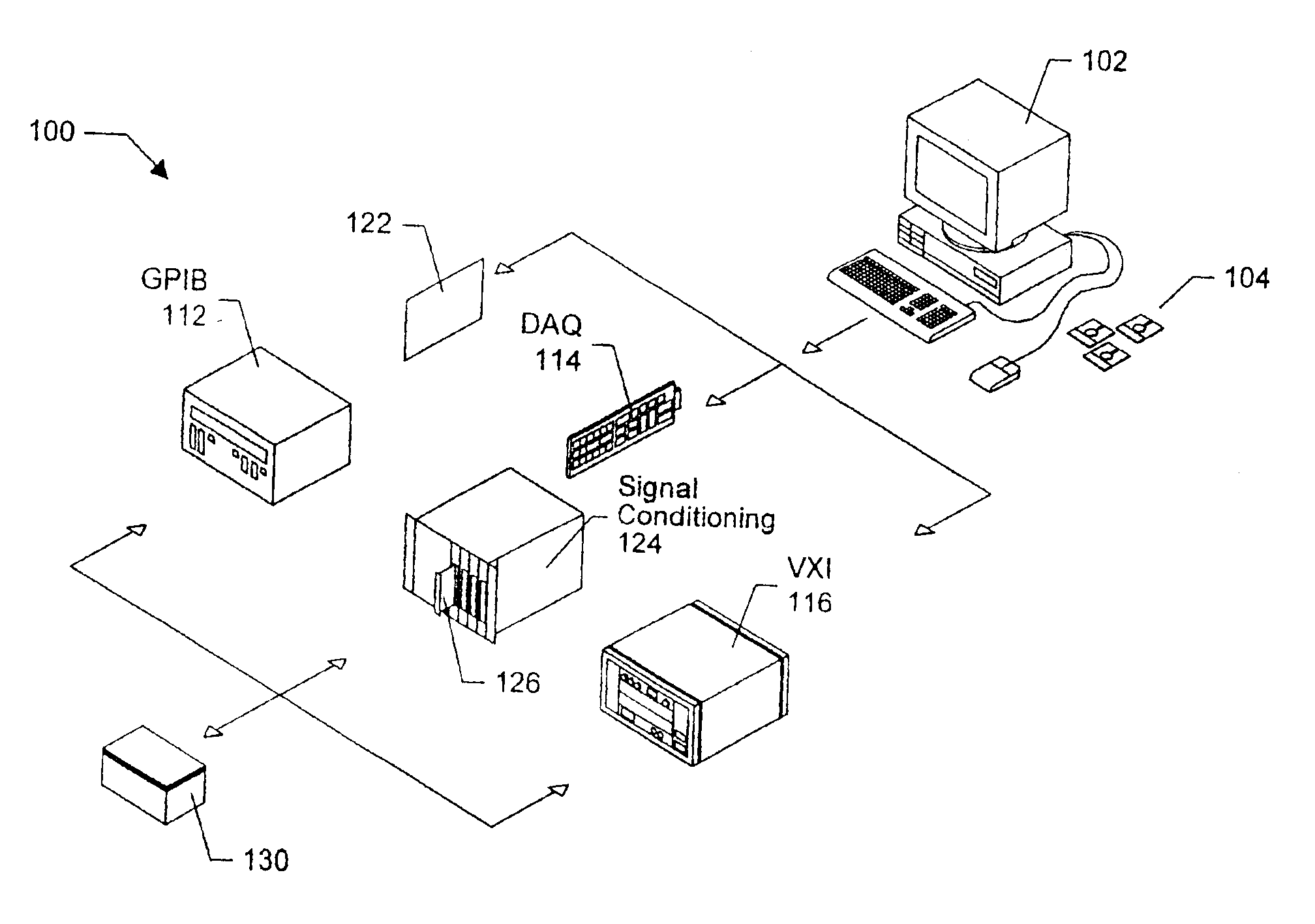
[0022]The present invention comprises a computer-implemented system and method for automatically generating hardware level functionality, e.g., programmable hardware or FPGAs, in response to a graphical program

Problems solved by technology

When traditional text-based programming environments are used, the user's programming skills and ability to interact with the computer system often become a limiting factor in the achievement of optimal utilization of the computer system.
There are numerous subtle complexities which a user must master before he can efficiently program a computer system in a text-based environment.
The task of programming a computer system to model a process often is further complicated by the fact that a sequence of mathematical formulas, mathematical steps or other procedures customarily used to conceptually model a process often does not closely correspond to the traditional text-based programming techniques used to program a computer system to model such a process.
Since a user often is not fully proficient in techniques for programmi

Method used


Image

  • Specifying and targeting portions of a graphical program for execution by multiple targets
  • Specifying and targeting portions of a graphical program for execution by multiple targets
  • Specifying and targeting portions of a graphical program for execution by multiple targets

Examples


Embodiment Construction

Incorporation by Reference

[0050]The following U.S. patents and patent applications are hereby incorporated by reference in their entirety as though fully and completely set forth herein.

[0051]U.S. Pat. No. 4,901,221 titled “Graphical System for Modeling a Process and Associated Method,” issued on Feb. 13, 1990.

[0052]U.S. Pat. No. 4,914,568 titled “Graphical System for Modeling a Process and Associated Method,” issued on Apr. 3, 1990.

[0053]U.S. Pat. No. 5,481,741 titled “Method and Apparatus for Providing Attribute Nodes in a Graphical Data Flow Environment”.

[0054]U.S. patent application Ser. No. 08 / 292,091 filed Aug. 17, 1994, titled “Method and Apparatus for Providing Improved Type Compatibility and Data Structure Organization in a Graphical Data Flow Diagram”.

[0055]U.S. Pat. No. 5,475,851 titled “Method and Apparatus for Improved Local and Global Variable Capabilities in a Graphical Data Flow Program”.

[0056]U.S. Pat. No. 5,497,500 titled “Method and Apparatus for More Efficient Fu...


PUM


Abstract

A computer-implemented system and method for generating a hardware implementation of graphical code. The method comprises first creating a graphical program. A first portion of the graphical program may optionally be compiled into machine code for execution by a CPU. A second portion of the graphical program is converted into a hardware implementation according to the present invention. The operation of converting the graphical program into a hardware implementation comprises exporting the second portion of the graphical program into a hardware description, wherein the hardware description describes a hardware implementation of the second portion of the graphical program, and then configuring a programmable hardware element utilizing the hardware description to produce a configured hardware element. The configured hardware element thus implements a hardware implementation of the second portion of the graphical program.

Description

CONTINUATION DATA[0001]This application is a Continuation of U.S. patent application Ser. No. 09 / 788,104 filed on Feb. 16, 2001 titled “System and Method for Configuring a Device to Perform Measurement Functions Utilizing Conversion of Graphical Programs into Hardware Implementations”, whose inventors are Jeffrey L. Kodosky, Hugo Andrade, Brian Keith Odom and Cary Paul Butler, which is a continuation of U.S. patent application Ser. No. 08 / 912,427 filed on Mar. 22, 2000 titled “System and Method for Converting Graphical Programs Into Hardware Implementations”, whose inventors are Jeffrey L. Kodosky, Hugo Andrade, Brian Keith Odom and Cary Paul Butler, which issued as U.S. Pat. No. 6,219,628 on Apr. 17, 2001, and which is a Continued Prosecution Application of U.S. patent application Ser. No. 08 / 912,427 filed on Aug. 18, 1997 titled “System and Method for Converting Graphical Programs into Hardware Implementations”, whose inventors are Jeffrey L. Kodosky, Hugo Andrade, Brian Keith Odo...

Claims


Application Information

Patent Timeline
IPC IPC(8): G06F11/273G06F17/50
CPCG06F8/34G06F11/2294G06F11/2733G06F17/5054G06F2217/74G06F30/34G06F2111/12
Inventor KODOSKY, JEFFREY L.ANDRADE, HUGOODOM, BRIAN K.BUTLER, CARY P.
Owner NATIONAL INSTRUMENTS
Why Eureka
Try Eureka