
Wheel bearing assembly for motor vehicles

a technology for motor vehicles and bearings, applied in bearing units, bearing rigid support, bearing cooling, etc., can solve the problems of reducing unable to use standardized normal bearings, and unable to manufacture bearing casings, etc., to achieve optimal mechanical properties, reduce the mechanical stability of stop protrusions, and low cost

Inactive Publication Date: 2005-08-30
VISTEON GLOBAL TECH INC
View PDF21 Cites 14 Cited by
  • Summary
  • Abstract
  • Description
  • Claims
  • Application Information

AI Technical Summary

Benefits of technology

[0011]Particular advantages are achieved when the bearing is press fit into the bearing casing, since press-fitting provides a relatively firm seat of the bearing within the casing and the mechanical stability of the stop protrusions may be reduced as a result thereof.
[0014]In configuring the supporting surface of the casing to form a shoulder, a particularly simple geometrical configuration of the casing may be realized which provides advantages in the manufacturing process of the casing.

Problems solved by technology

The disadvantage of this construction is that the recesses on the inner circumference of the bearing casing make it more difficult to manufacture the bearing casing.
Furthermore, it is not possible to use standardized normal bearings because of the recesses required on the outer ring of the bearing.
However, this requires an additional machining step, which precludes low cost industrial scale production.
Furthermore, the retention force of such a snap ring is limited.
However, particular precautionary measures must be taken so that but small mechanical forces are allowed to act onto the outer ring portion while the flange of the projection is being formed in order to prevent the outer ring portion from being deformed, which would reduce the mechanical durability of the bearing.
Finally, during the manufacturing process of the bearing casing, the thin-walled, plastically deformable projection must be additionally molded with a special constriction to form the flange, which makes production technically more complicated.

Method used


Image

  • Wheel bearing assembly for motor vehicles
  • Wheel bearing assembly for motor vehicles
  • Wheel bearing assembly for motor vehicles

Examples


Embodiment Construction

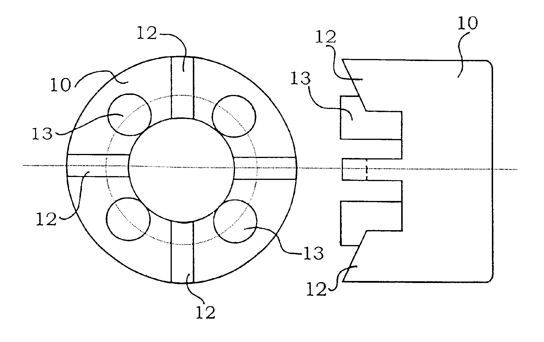
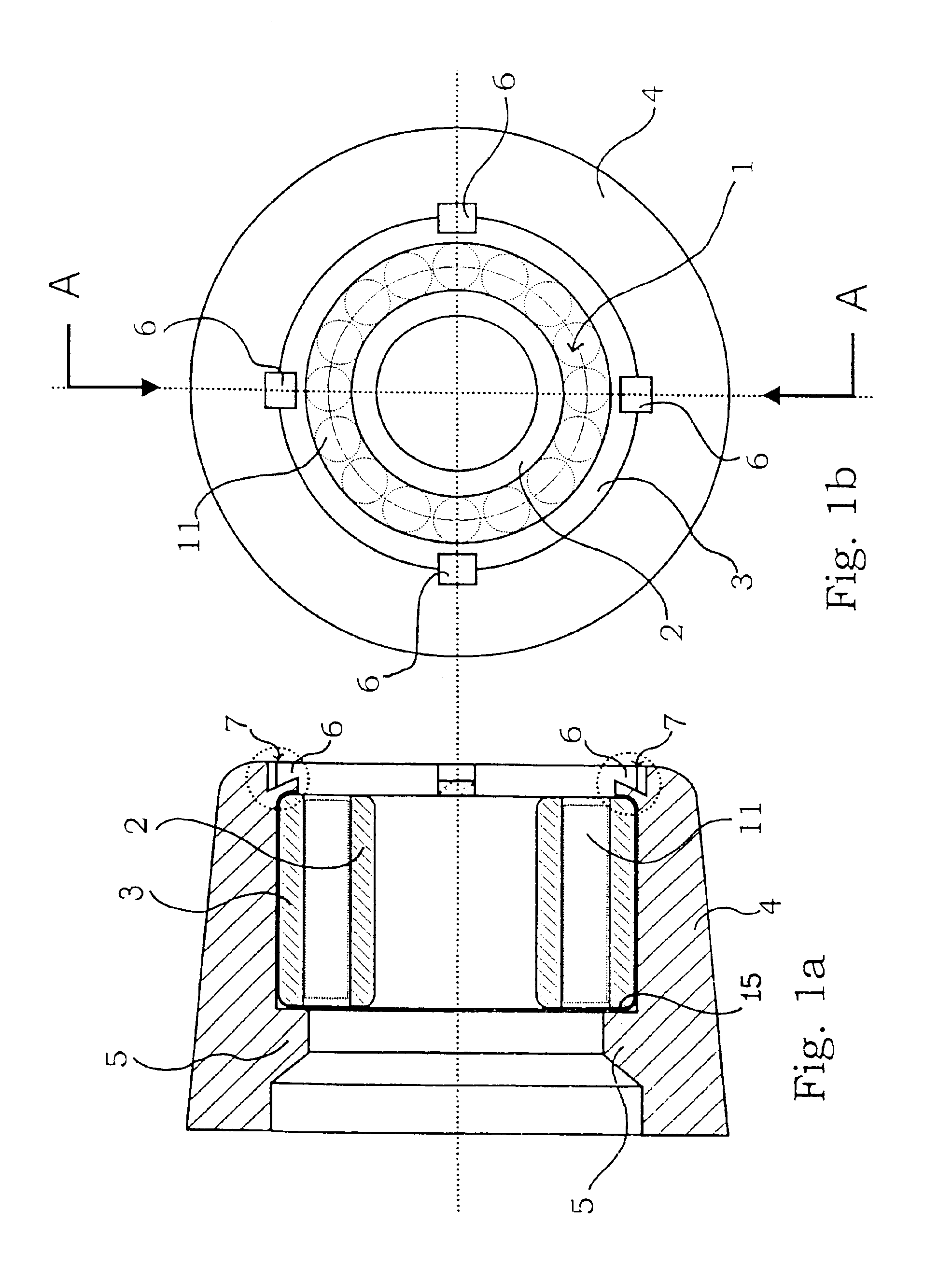
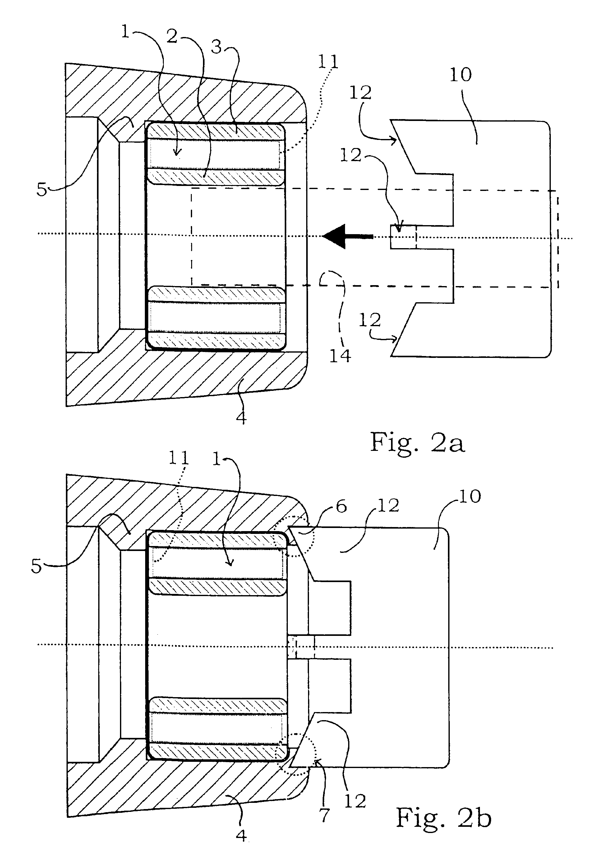
[0037]The FIGS. 1a and 1b are sectional and end views, respectively, of a first exemplary embodiment of a wheel bearing assembly for motor vehicles in accordance with the invention. FIG. 1a is a sectional view of the wheel bearing assembly taken along line A—A of FIG. 1b. The wheel bearing assembly of the invention consists of a bearing casing 4 made from gray cast iron. A bearing 1 is fitted in said bearing casing 4 with its outer ring 3. Bearing 1 may be a rolling contact bearing with rolling elements 11 configured to form cylindrical rollers. Said rolling elements 11 are illustrated in FIG. 1b, they are denoted as a dotted rectangle in FIG. 1a. They are also denoted as a dotted rectangle in the FIGS. 2a, 2b, 5a, 5b, 6b, 7a, 7b and 8b.

[0038]For fitting bearing 1, the inner circumference of bearing casing 4 is machined down in a preparation step or otherwise formed with an inner diameter for the purpose of providing a fit between bearing casing 4 and outer ring 3 of bearing 1, per...


PUM

PropertyMeasurementUnit
Forceaaaaaaaaaa
Circumferenceaaaaaaaaaa
Displacementaaaaaaaaaa

Abstract

The invention relates to a wheel bearing assembly for motor vehicles with a bearing provided with an inner ring and an outer ring, the bearing being fitted with its outer ring into a bearing casing and the outer ring being mechanically supported in axial direction on a first side by a supporting surface provided on the bearing casing. Discrete and preferably evenly arranged stop protrusions are formed on the inner circumference of the bearing casing, the outer ring abutting thereon in axial direction on its second side, and the stop protrusions being formed by locally plastic forming the bearing casing.

Description

BACKGROUND OF THE INVENTION[0001]1. Field of the Invention[0002]The subject matter of the present invention is a wheel bearing assembly for motor vehicles and a method for manufacturing such a wheel bearing assembly.[0003]2. Description of Related Art[0004]Such wheel bearings are comprised of a bearing, a rolling contact bearing for example, with an inner ring and an outer ring. With its outer ring, the bearing is fitted into a casing. In order to ensure proper operation of the wheel bearing assembly, the outer ring of the bearing assembly must be fixed within the casing. According to prior art, the bearing assembly is press-fitted within the casing in the simplest case. In spite of this press-fit connection, axial clearance of the bearing within the casing is still possible.[0005]DE 199 29 536 C1 discloses an arrangement for axially fixating the ring of a bearing by means of an annular fixation element. Said fixation element is divided into several sections around the circumference...

Claims


Application Information

Patent Timeline
IPC IPC(8): B23P11/00B60B27/00F16C35/04F16C35/067B21D39/00F16C19/26F16C37/00
CPCB23P11/005F16C35/067B60B27/02F16C19/26Y10T29/497Y10T407/1614Y10T29/49936Y10T29/49771Y10T407/16Y10T29/49696Y10T29/53109Y10T409/40Y10T409/400175Y10T29/49995Y10T409/4077Y10T29/49686Y10T29/49915F16C35/042F16C2326/02F16C2226/52
Inventor FRANTZEN, MICHAEL JOHANNES
Owner VISTEON GLOBAL TECH INC
Learn More