Microphone shroud and related method of use

a microphone and shroud technology, applied in the field of microphone shrouds and shrouds, can solve the problems of foam deterioration, noise adversely affecting the performance of the microphone in terms of sound quality transmission, and the general exposure of the microphone to extremely harsh environmental conditions

Inactive Publication Date: 2005-08-30
OWENS THOMAS G
View PDF19 Cites 26 Cited by
  • Summary
  • Abstract
  • Description
  • Claims
  • Application Information

AI Technical Summary

Benefits of technology

[0016]According to the preferred embodiment of the present invention, there is provided a contoured enclosure or shroud for mounting over a microphone. The shroud includes a closed end, an open end that is substantially opposite the closed end, and an intermediate portion therebetween. Between the open and closed ends, the intermediate portion of the shroud defines a mouth opening for facing a user's mouth. Substantially opposite the mouth opening of the shroud is disposed a portion of the shroud that is impermeable to airflow so that wind does not directly impinge on the microphone. Preferably, the shroud mounts over a windsock that is mounted over the microphone. The shroud can also include a resilient fastener that is secured to a portion of the front end of the shroud so that the shroud more snugly mounts around the microphone. As such, the shroud shields the microphone from harsh environmental conditions such as wind and rain.

Problems solved by technology

These microphones are generally exposed to extremely harsh environmental conditions including wind noise, traffic noise, and vibrational noise.
Such noise adversely affects performance of microphones in terms of sound quality transmission.
One disadvantage with this approach is that the foam tends to deteriorate under exposure to the outdoor environment.
A more significant disadvantage is that foam windsocks tend to be effective only up to a certain minimal wind velocity.
Therefore, the Knutson et al. solution is not effective under high air turbulence where there are relatively high winds or where the microphone is moving at a high rate of speed.
Unfortunately, however, Das et al. does not fully solve the problems with the Knutson et al. reference.
The foam layer is still not effective under high air turbulence regardless of the dead layer of air and the heavily perforated sphere.
A disadvantage, however, is that the Staple et al. microphone lacks the benefits of a foam windsock.
Another disadvantage is that the Staple et al. microphone is specially and newly designed and is not adaptable to already existing and readily available microphones.
Thus, the Staple et al. microphone is a cost prohibitive solution to the above-mentioned problems in the prior art.
Unfortunately, such high-tech, high-cost approaches involving noise filtering and canceling do not sufficiently attenuate environmental noises, especially wind noise.
In fact, these electronic approaches usually reduce environmental noise but do so at the expense of attenuating desired sound signals, and degrading sound clarity and overall quality.
Motorcycle helmet headsets are particularly susceptible to environmental noises including that from headwind, crosswind, nearby traffic, tunnel echoes, and motorcycle engine noise.
Unfortunately, however, environmental noise is a significant problem for a couple of reasons.
First, the environmental noise degrades microphone transmission quality as discussed previously.
Additionally, the environmental noise tends to inadvertently interrupt radio signals being transmitted from the on-board AM / FM radio to the speakers of the headset.
Motorcycle riders tend to find this annoying and inconvenient.
VOX often misinterprets environmental noise as desired speech and cuts out the radio signal, subordinating it to the headset communication system.
Unfortunately, such a solution amounts to yet another of the many electronic signal processing techniques, which are not fully adequate to solve the environmental noise problems of the prior art, as discussed above.
From the above, it can be appreciated that microphone devices of the prior art are not fully optimized to adequately suppress unwanted environmental noise.

Method used


Image

  • Microphone shroud and related method of use
  • Microphone shroud and related method of use

Examples


Embodiment Construction

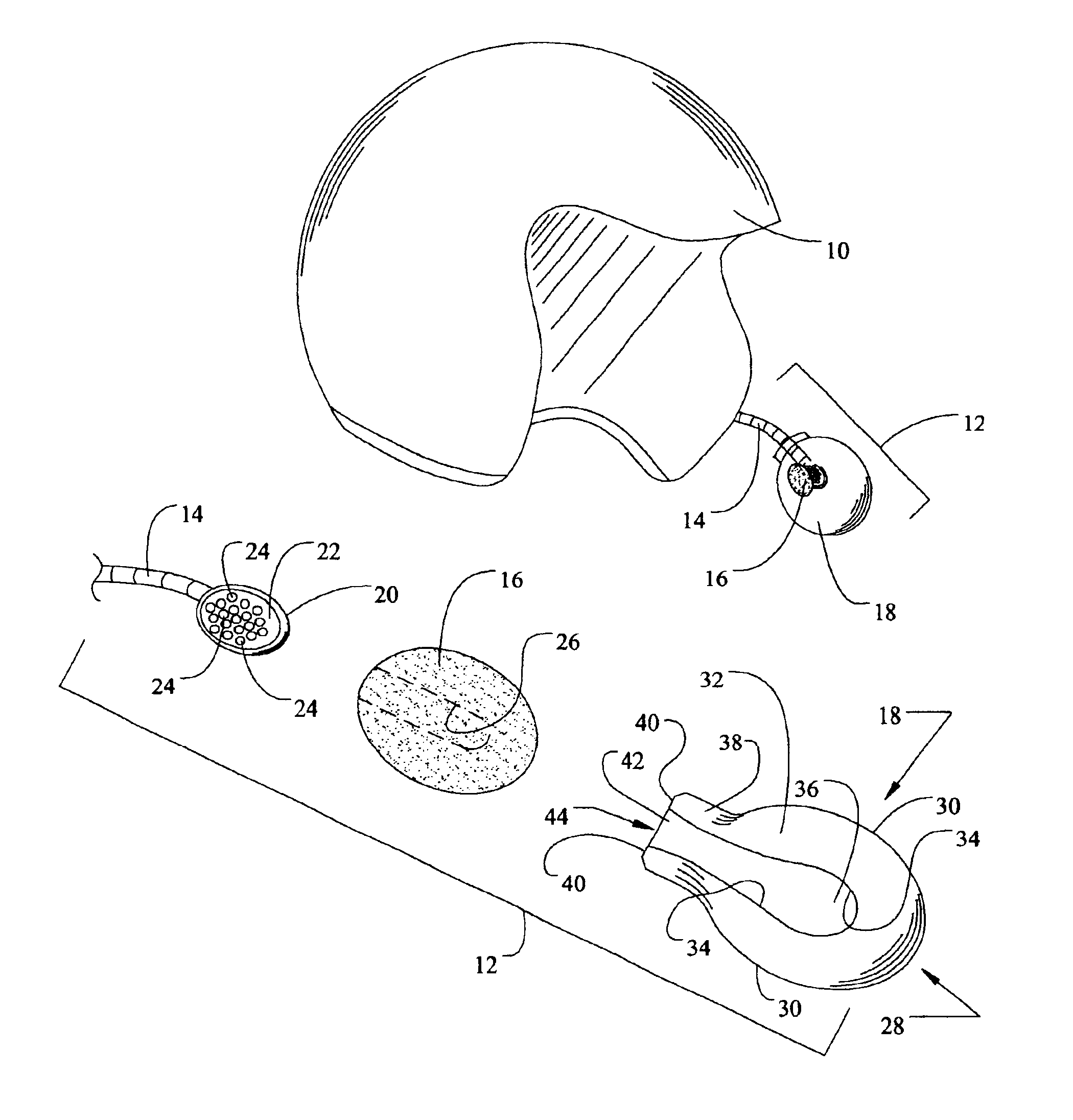
[0028]Generally, a microphone shroud in accordance with the present invention is shown in the Figures in conjunction with a typical helmet mounted headset including a microphone. The term shroud is basically synonymous with the terms enclosure, deflector, cover, boot, body, baffle, etc.

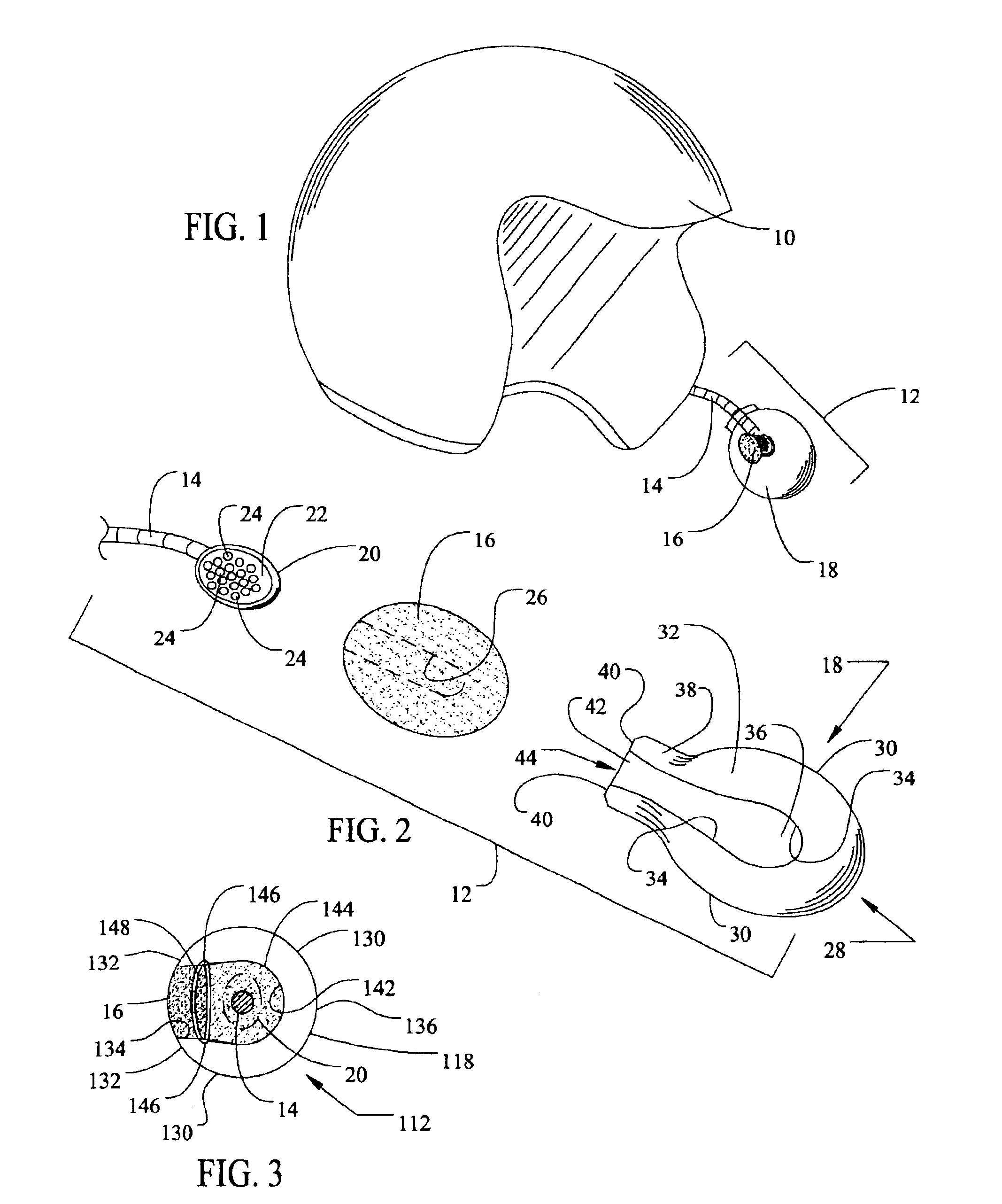
[0029]Referring now in detail to the Figures, there is shown in FIG. 1 a ¾ open-faced helmet 10 having a microphone assembly 12 attached thereto. The microphone assembly 12 is part of a complete headset (not entirely shown) that includes earphones positioned inside the helmet 10. A complete headset is typified by the AeroMike® III helmet headset available from the J&M Corporation for between $120 and $220. The microphone assembly 12 generally includes a flexible boom 14, a microphone (not shown) attached to and terminating the flexible boom, a windsock 16, and a shroud 18.

[0030]As specifically shown in FIG. 2, the microphone assembly 12 also includes a microphone 20 that has a back surface 22 with ope...


PUM


Abstract

A shroud and method capable of attenuating undesirable environmental noise from reaching a microphone. The shroud is a cover including a closed end, an open end substantially opposite of the closed end, and an intermediate portion that extends away from the closed end toward the open end. The intermediate portion includes a back side with a mouth opening that faces a user's mouth. The intermediate portion further includes a front side that is substantially opposite of the back side, with the front side being impermeable to airflow. Preferably, the shroud mounts over a windsock that mounts over the microphone. A flexible fastener may be secured to a portion of the open end so that the shroud more snugly mounts around the microphone. As such, the shroud shields a microphone from harsh environmental conditions such as wind and rain.

Description

CROSS-REFERENCES TO RELATED APPLICATIONS[0001]Not applicable.FEDERALLY SPONSORED RESEARCH OR DEVELOPMENT[0002]Not applicable.REFERENCE TO A MICROFICHE APPENDIX[0003]Not applicable.BACKGROUND OF THE INVENTION[0004]1. Field of the Invention[0005]The present invention generally relates to microphone technology. More specifically, this invention is directed to a shroud, and related method, for mounting over a helmet-mounted microphone, such that undesirable environmental noise is attenuated, yet desired input signals are not so attenuated.[0006]2. Description of the Related Art[0007]Outdoor microphones are widely used in various applications by various people including television reporters, public addressers, movie makers, and motorcycle riders. These microphones are generally exposed to extremely harsh environmental conditions including wind noise, traffic noise, and vibrational noise. Such noise adversely affects performance of microphones in terms of sound quality transmission. There...

Claims


Application Information

Patent Timeline
Patent Type & Authority Patents(United States)
IPC IPC(8): H04R1/08
CPCH04R1/086
Inventor OWENS, THOMAS G.
Owner OWENS THOMAS G
Why Eureka
Try Eureka