Electronically-operable door strike with guard clip, springless solenoid and face plate

Inactive Publication Date: 2005-08-30
TRINE ACCESS TECH
View PDF4 Cites 28 Cited by
  • Summary
  • Abstract
  • Description
  • Claims
  • Application Information

AI Technical Summary

Benefits of technology

[0012]For the foregoing reasons, there is a need for an electric strike which overcomes the hereto before described problem of residual magnetism associated with a frequently cycled or continuous duty solenoid plunger. There is a further need for an electric strike in which a tool cannot be used to pry

Problems solved by technology

The stop lever, no longer being engaged by and being held in position by the lock lever, is incapable of resisting pivoting of the latch bolt keeper when force is applied to the keeper.
One drawback of some of the electric strikes heretofore available is the ease with which they can be picked open and defeated by the insertion of a tool for unauthorized movement of the latch bolt keeper to a latch bolt releasing position.
Another disadvantage of the electric strikes heretofore available is the undesirable build-up of residual magnetism within the solenoid or on the solenoid plunger.
Build-up of residual magnetism during repeated cycling of the solenoid results in the eventual failure of the solenoid's ability to remotely disengage the lock lever and the stop lever so as to permit the latch bolt keeper to be rotated and the access obstructing member opened.
Upon the build-up of residual magnetism along the plunger or solenoid body, however, the plunger can remain in contact with the lock lever or not fully exit the body of the solenoid, thus compromising the ability of the lock lever to disengage from the stop lever.
Again, however, upon the build-up of residual magnetism along the plunger, the plunger may not be able to be completely returned to its starting position by the spring

Method used


Image

  • Electronically-operable door strike with guard clip, springless solenoid and face plate
  • Electronically-operable door strike with guard clip, springless solenoid and face plate
  • Electronically-operable door strike with guard clip, springless solenoid and face plate

Examples


Embodiment Construction

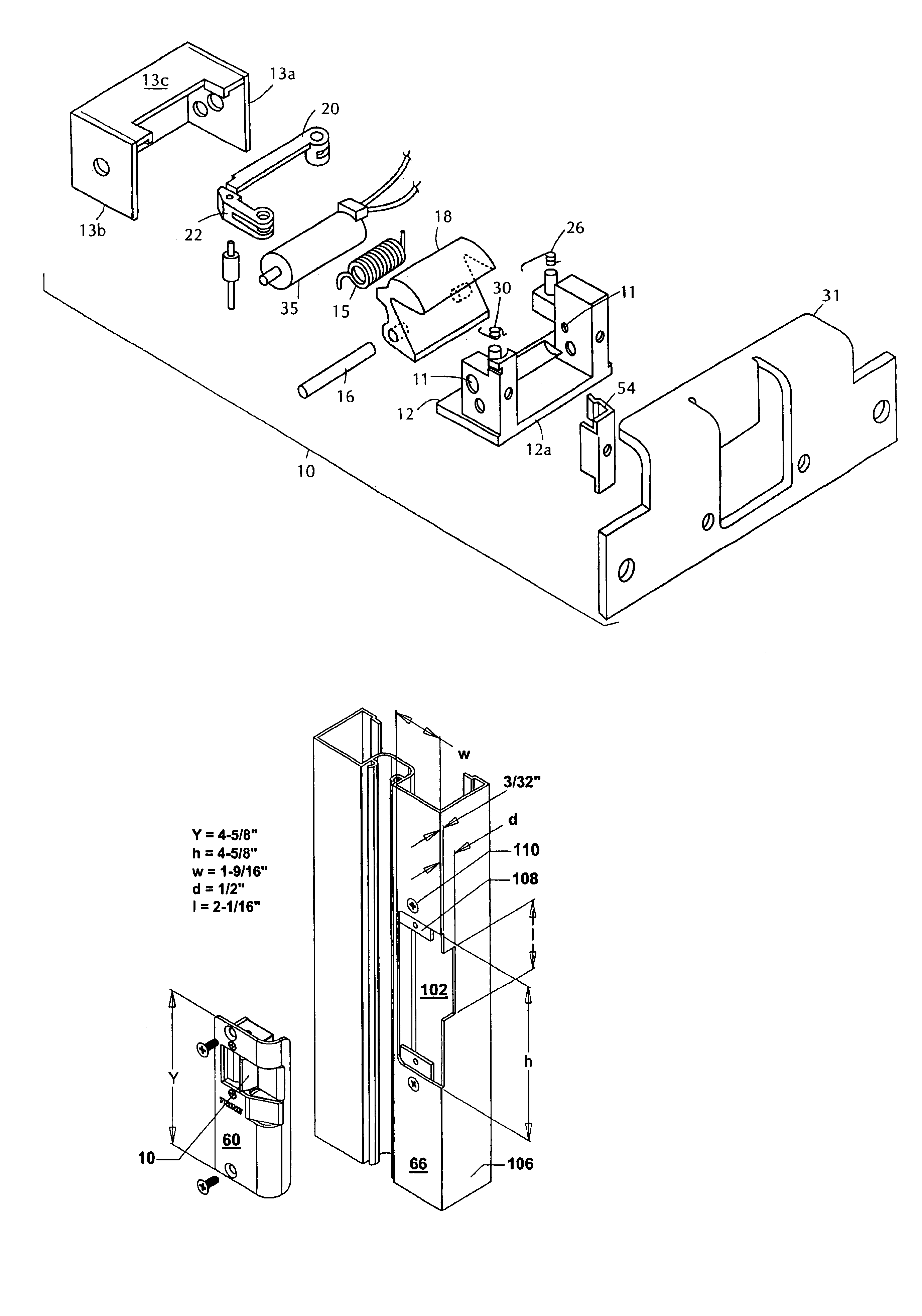
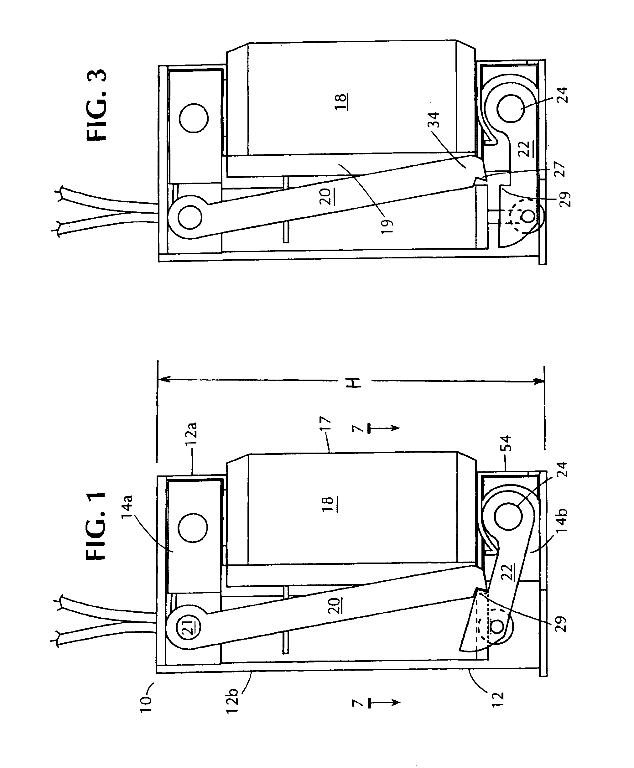
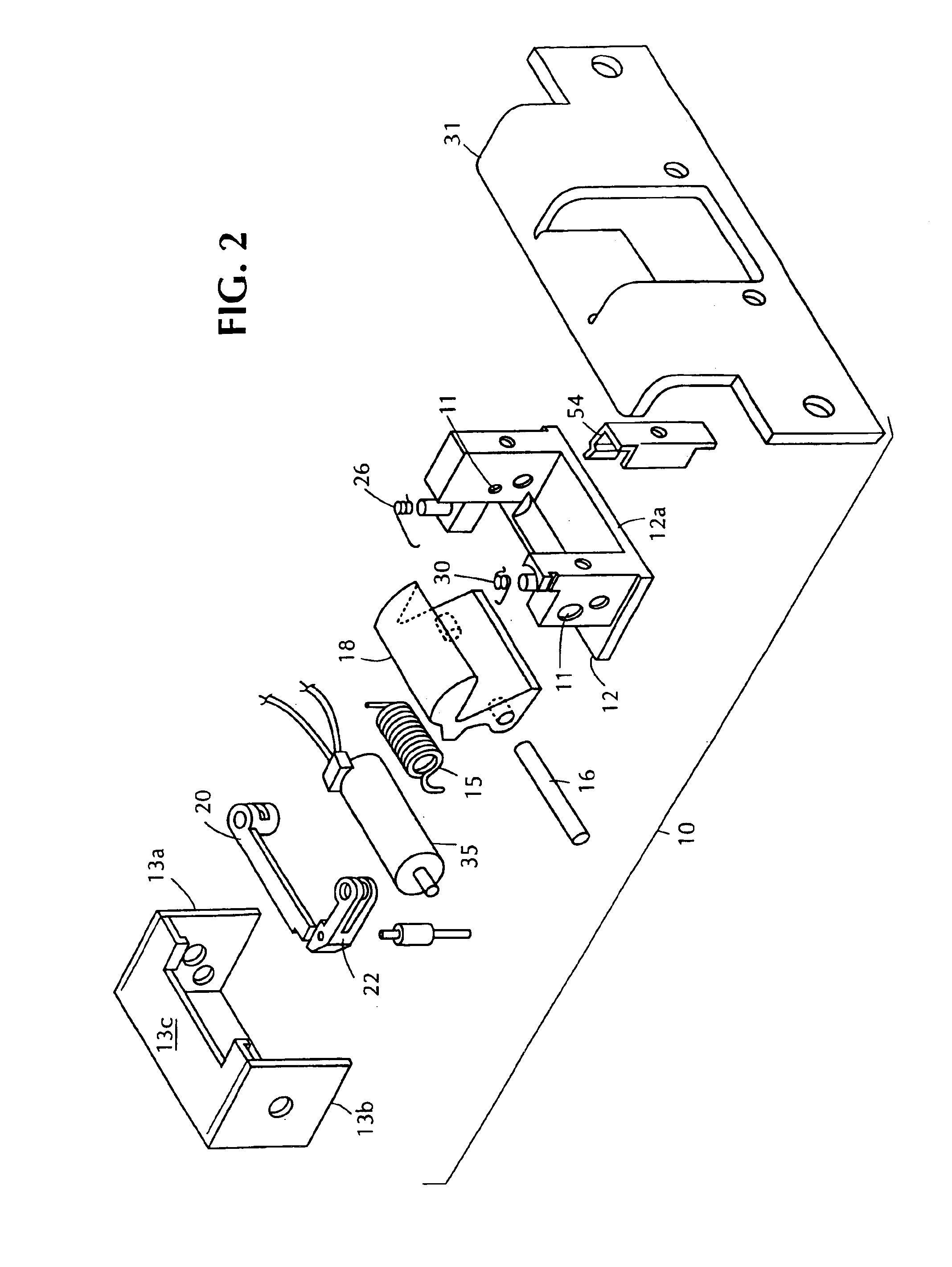
[0042]Referring now to the drawings there is shown in FIG. 1 an electrically-operable door strike as generally indicated by the numeral 10. The electric strike is comprised of a base 12 having a front edge 12a and a rear edge 12b. To base 12 are fixedly secured a pair of spaced-apart support blocks 14a and 14b each provided with threaded openings 11 (see FIG. 2) for receiving screws to fixedly hold a pair of end panels 13a and 13b and a cover 13c. Support blocks 14a and 14b also carry a shaft pin 16 (see FIG. 2) for rotatably supporting a latch bolt keeper 18. The cross-sectional configuration of the latch bolt keeper may best be observed in FIG. 7. Mounted circumferentially around shaft pin 16 is a cylindrical turning spring 15 which urges the latch bolt keeper 18 into its latch bolt securing position wherein the front edge portion 17 of latch bolt keeper 18 protrudes beyond front edge 12a of base 12 (as best seen in FIG. 1), through face plate 31 (FIG. 2) and engages the latch bol...


PUM


Abstract

An electronically-operable door strike employing a guard clip for deterring picking of the locking mechanism therein, a springless solenoid designed to avoid the undesirable build-up of residual magnetism and which incorporates air gaps for dissipating heat, thus prolonging the useful life of the solenoid, and a face plate for mounting the strike into a door jamb.

Description

[0001]This is a continuation-in-part of application Ser. No. 10 / 039,472, filed Jan. 4, 2002, now U.S. Pat. No. 6,634,685.BACKGROUND OF THE INVENTION[0002]1. Field of the Invention[0003]The present invention is directed to door locking devices and, more particularly, to electromagnetically controlled door locks that are actuatable from remote locations throughout a building. Such locks, known generally as “electric strikes”; are commonly used to prevent the opening of an associated access obstructing member, such as a door, in hotels, offices, apartment buildings, storage cabinets and appliances. In a preferred embodiment the electric strike of the present invention employs a guard clip for deterring picking of the locking mechanism, a springless solenoid designed to prevent the build-up of residual magnetism which otherwise impairs a solenoid's ability upon activation to release the locking mechanism, and a one piece face plate for mounting in a doorjamb which serves to house the el...

Claims


Application Information

Patent Timeline
IPC IPC(8): E05B47/00
CPCE05B47/0047Y10T292/699
Inventor SCHILDWACHTER, WILLIAMFRUSSINETTY, CARLOORBETA, FRED
Owner TRINE ACCESS TECH
Why Eureka
Try Eureka