Seat suspension

Active Publication Date: 2005-08-30
MILSCO LLC
View PDF57 Cites 56 Cited by
  • Summary
  • Abstract
  • Description
  • Claims
  • Application Information

AI Technical Summary

Benefits of technology

[0023]As a consequence of the configuration of the suspension, the transfer link has one additional degree of freedom of movement, namely, in a generally lateral direction along the transfer link surface engaged by the movable pivot pin. To prevent or constrain the motion of the transfer link in this direction, the transfer link includes a slide pin that extends outwardly from the transfer link and that is received within a curved slot formed in the suspension base or ground which guides the slide pin and consequently the transfer link as they rotate around the movable pivot pin. More particularly, the curved slot in the suspension base that is formed to conform to the rotary path of that transfer link will take about any location of the movable pivot pin with respect to the transfer link to provide pure arcuate movement to the transfer link as the suspension operates. Further, to provide smooth arcuate movement of the slide pin, the slide pin carries a bearing that is received in the slot and that provides an amount of lubricity and wear resistance to the slide pin and the slot.
[0024]According to another aspect of the present invention, the weight adjustment mechanism is configured to enable an occupant to set the suspension at a number of separate positions corresponding generally to occupants of different, specified weights. In order to illustrate the weight at which the adjustment mechanism is set, the suspension can also include an optional indicator to identify the approximate weight of an occupant for which the suspension is currently configured so that an occupant can easily adjust the mechanism to the proper suspension setting. Further, the design of the adjustment mechanism has the desirable result that the mechanism is easy to operate, even for a seated occupant, and that the force required to move the weight adjustment mechanism between the separate positions is relatively minor. This low energ

Problems solved by technology

However, most seats constructed today are not capable of adjusting the amount of support provided to a wide range of operators in a manner that does not sacrifice the comfort, more specifically the vibration attenuation of the seat to a particular population of operators.
Since these attributes are generally not adjustable in low cost seat suspensions, vibration isolation is compromised over the mass adjustment range.
Seat vibration test standards such as ISO7096 can be difficult to pass with a nonadjustable spring rate and damping rate suspension.
The low damping rate in turn results in suspension end stop impacts causing the designer to either increase the damping at the expense of the light operator's vibration isolation or increase the suspension stroke at the expense of SIP (seat index point) height.
This is an undesirable result because the difference between the transmissibility curves implies that more effort is required to adjust the suspension than necessary, since during weight adjustment the heavy operator is gaining an advantage in isolation over the light operator.
Anot

Method used


Image

  • Seat suspension
  • Seat suspension
  • Seat suspension

Examples


first embodiment

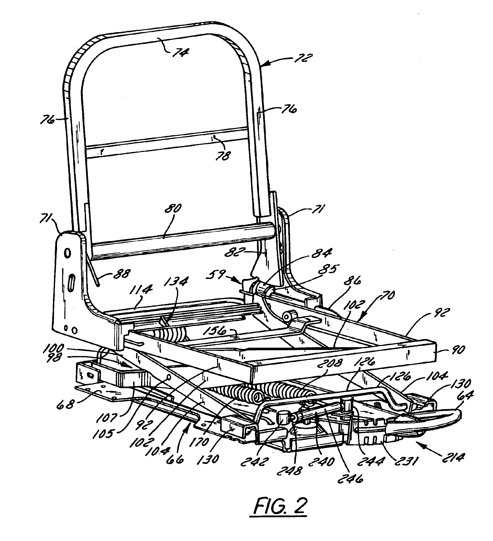
[0065]The second ends 124 each include an arcuate slot 132 extending therethrough that is adapted to receive and engage one end of a crossbeam 134. The crossbeam 134 is generally arcuate in cross-section and includes an upper lip 136 that is fixedly connected to each of the second ends 124 of the outer arms 104 in any conventional manner, such as by welding, and a lower lip 138 that extends between the outer arms 104. In a first embodiment, each end of the crossbeam 134 that extends through the arcuate slots 132 forms a receiver cup 140 which rotatably supports a shaft 142, as best shown in FIGS. 3-7. Opposite the cup 140, each shaft 142 is fixedly connected to the bracket 71 and side member 92 such that each shaft 142 forms a part of the seat frame 70. The engagement of the shaft 142 within the receiver cup 140 enables the cup 140 and the second end 124 of each outer arm 104 to move or pivot with respect to the shaft 142 and frame rail 70 when the frame rail 70 is depressed, conseq...

second embodiment

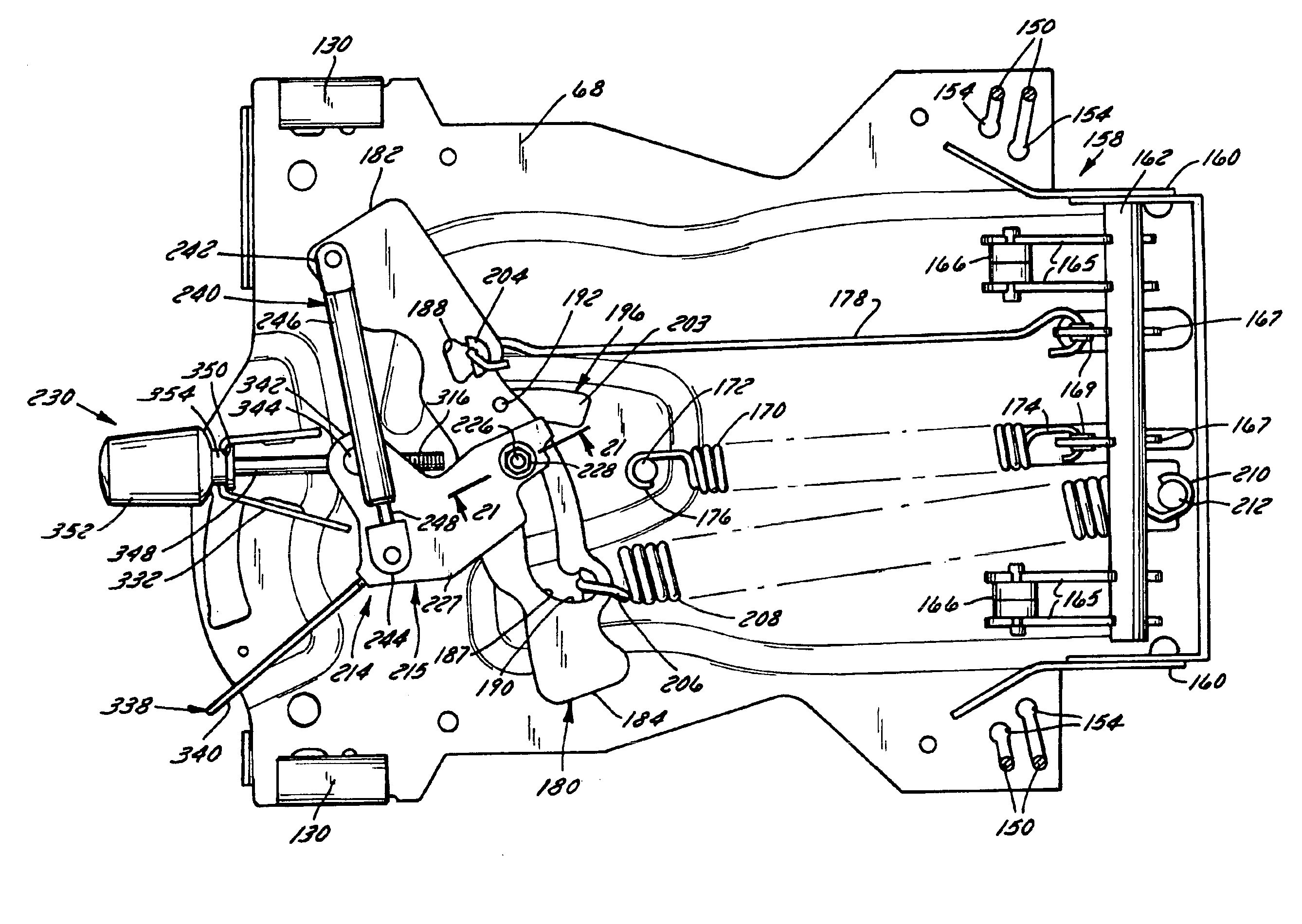
[0069]In the bellcrank 158 shown in FIGS. 15-19, the pivot rod 162 still extends between the supports 160, but instead of a single pair of roller supports 164, the rod 162 is connected to two spaced pairs of roller support arms 165 and a pair of pull arms 167 disposed between the pairs of roller support arms 165. Each pair of roller support arms 165 supports a roller 166 therebetween which is positioned directly beneath and in engagement with the lower lip 138 of the crossbeam 134. The pull arms 167 extend outwardly from the pivot rod 162 at an angle with regard to the supports arms 165, preferably less than ninety (90) degrees, with one pull arm 167 engaging the hook 174 on the first spring 170 and the other pull arm 167 engaging one end of the transfer rod 178. The pull arms 167 can include low-friction bearings 169 disposed between the arms 167 and the hook 174 and transfer rod 178, respectively, in order to enhance the ease of movement of the arms 167, hook 174 and rod 178 with ...


PUM


Abstract

A suspension for a seat that varies the preload, spring rate and damping rate of the suspension in direct proportion to the suspended weight of an occupant of the seat to provide the same effective vibration isolation for any occupant. The suspension includes an actuating mechanism engaged with a first spring and a pivotal transfer link that is engaged with a second spring and a non-adjustable rate damper that are each fixedly attached to the seat opposite the transfer link. The transfer link is engaged with a weight adjustment mechanism which operates to adjust the position of a pivot pin for the transfer link with respect to the transfer link, such that the preload, spring rate and damping rate of the suspension are adjusted in proportion to the weight of the occupant of the seat to provide similar ride dynamics to any occupant of the seat.

Description

CROSS REFERENCE TO RELATED APPLICATIONS[0001]This application claims priority from U.S. Provisional Patent Application Ser. No. 60 / 366,965, which was filed on Mar. 22, 2002.FIELD OF THE INVENTION[0002]The present invention is directed to a suspension for a seat and more particularly to a seat suspension that varies the preload, spring rate and damping rate of the suspension in proportion to the weight of the seat occupant.BACKGROUND OF THE INVENTION[0003]For an operator to efficiently control a piece of machinery, the seat which provides the operator an interface with the machine must be able to comfortably support the operator over an extended period of time. Over the years a number of different seat suspension designs have been developed to provide a comfortable support for an operator. In the majority of those designs, the seat suspensions are constructed to have the amount of resistance or support provided, and the vertical position of the seat adjusted to accommodate the weight...

Claims


Application Information

Patent Timeline
IPC IPC(8): B60N2/50B60N2/54B61D33/00
CPCB60N2/502B60N2/503B60N2/504B60N2/505B60N2/506B60N2/508B60N2/509B60N2/544B60N2/50
Inventor JANSCHA, RYAN DERRICKHILL, KEVIN EARLDAVIS-TROLLER, DEANBOYLES, BRADLEY S.KUCHARSKI, JOHN
Owner MILSCO LLC
Why Eureka
Try Eureka