High stiffness composition tool bar

a composition tool bar and high-strength technology, applied in the field of machining tool bars, can solve the problems of high manufacturing cost of tool bars exhibiting optimum performance, high cutting speed and feed rate thresholds, and inability to machine deep holes, etc., and achieve high stiffness and high stiffness

Inactive Publication Date: 2005-08-30
KOREA ADVANCED INST OF SCI & TECH +1
View PDF17 Cites 17 Cited by
  • Summary
  • Abstract
  • Description
  • Claims
  • Application Information

AI Technical Summary

Benefits of technology

[0004]Therefore, an object of the present invention is to provide a high stiffness composite tool bar using high stiffness composite material capable of substituting for a conventional boring and reaming bars which have been made of tungsten carbide alloy and tool steel.

Problems solved by technology

Accordingly, upper thresholds of a cutting speed and a feed rate are low, and it is impossible to machine a deep hole.
However, since it is difficult to machine cemented carbide, there is a disadvantage in that manufacturing costs of a tool bar exhibiting optimum performance become very high.
Further, since the natural frequency of a boring bar or a reaming bar is low due to high densities of tungsten carbide and tool steel, there is a limitation on improvement of the cutting speed of the bar.

Method used


Image

  • High stiffness composition tool bar
  • High stiffness composition tool bar
  • High stiffness composition tool bar

Examples


first embodiment

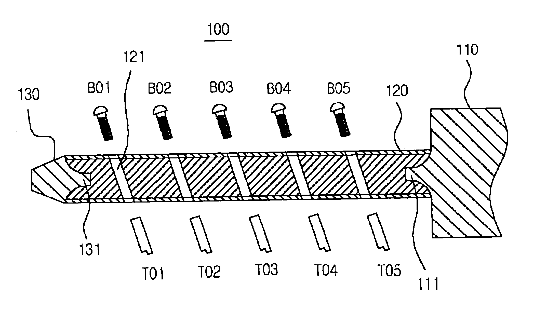
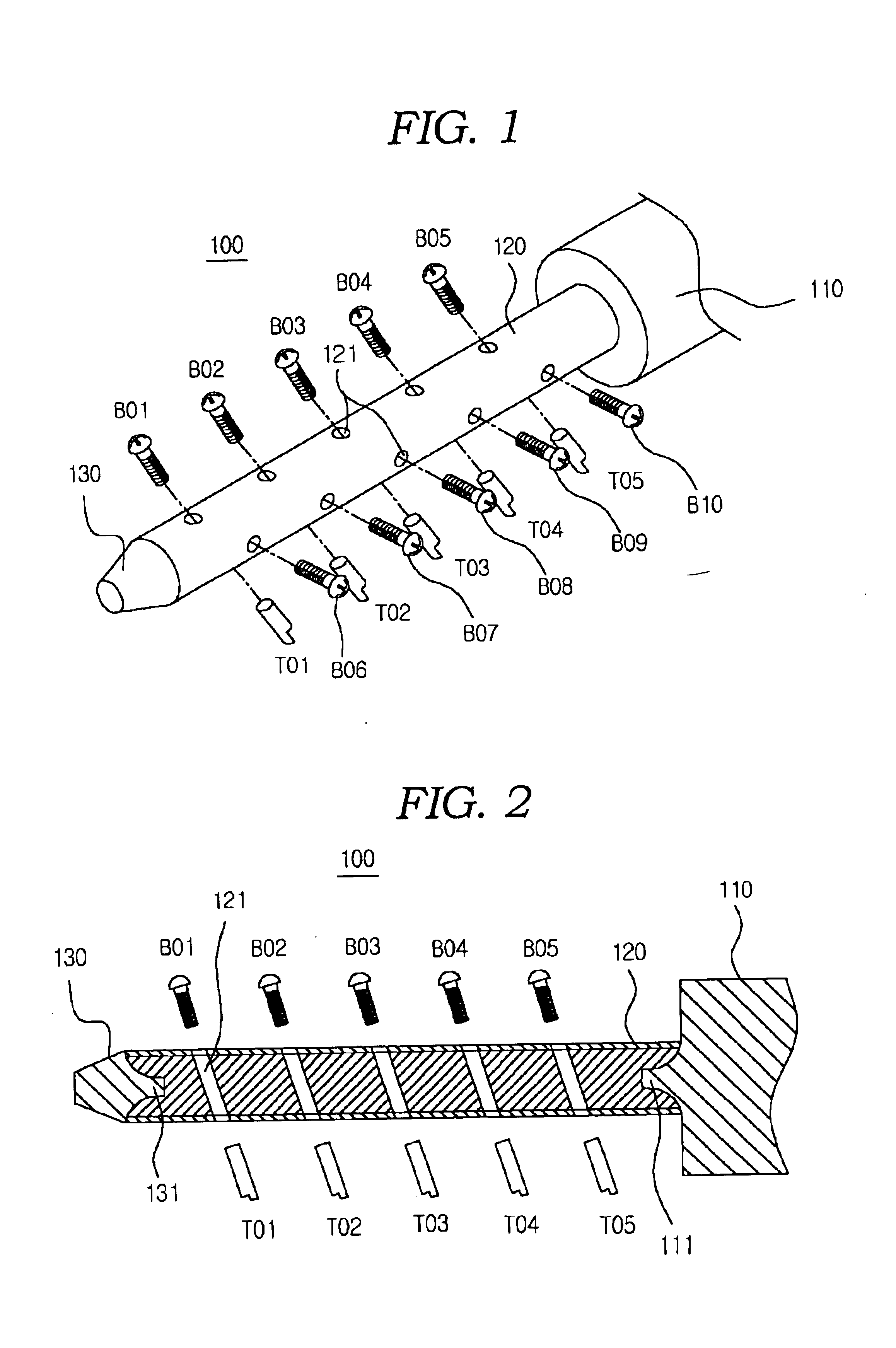
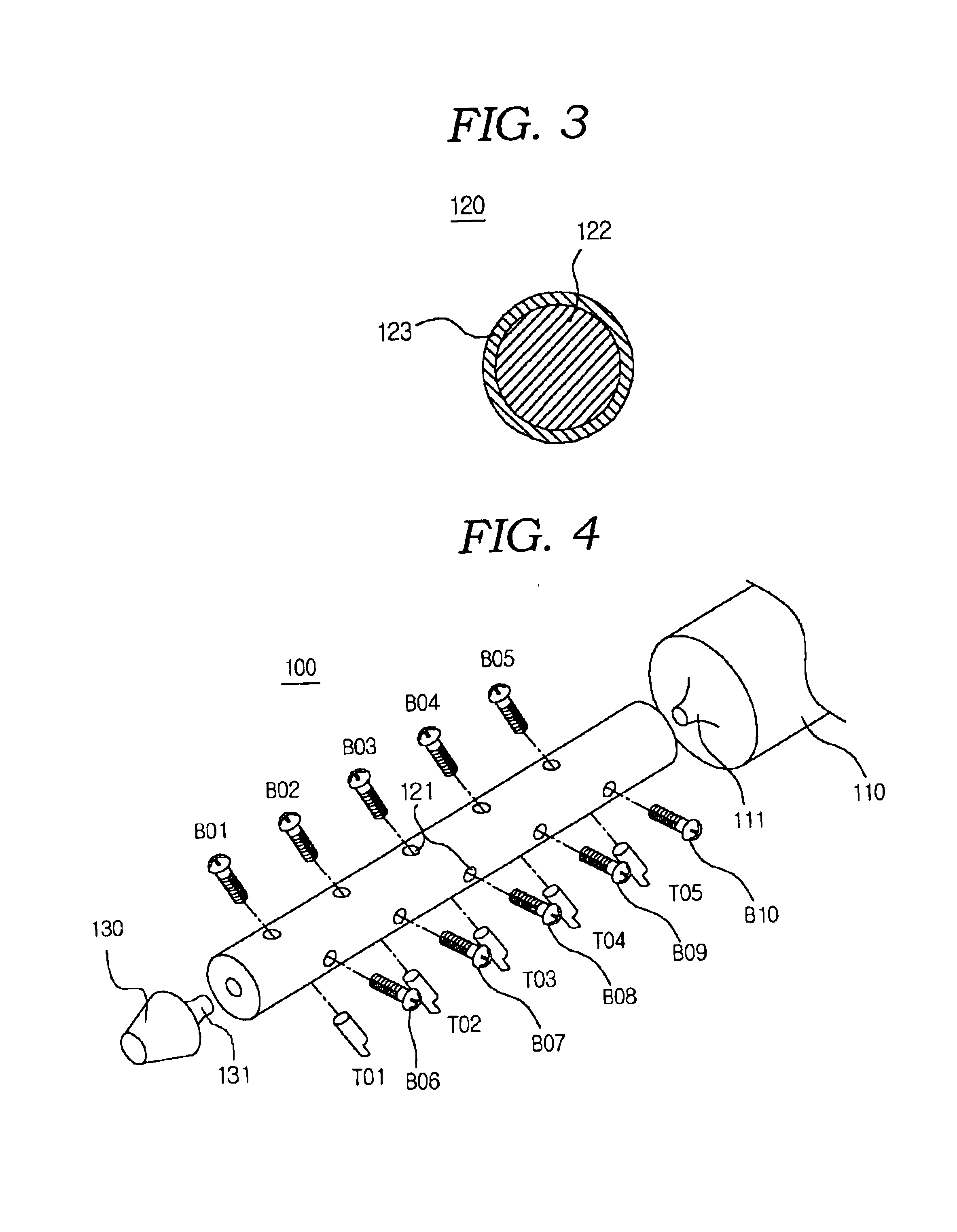
[0023]FIGS. 1 to 4 show a tool bar according to the present invention.

[0024]As shown in FIG. 1, a tool bar 100 is functionally divided into an adaptor 110 constructed to be coupled to a driving device, a body 120 constructed to be mounted with cutting tools, and a tip 130 constructed to be supported by a workpiece. The body 120 can be mounted with a plurality of cutting tools. Here, there is exemplified the tool bar 100, which can be mounted with five cutting tools T01 to T05 along a longitudinal axis of the body 120.

[0025]The adaptor 110 and tip 130 of the tool bar 100 according to this embodiment are made of tool steel, and the body 120 is made of carbon fiber composite material having high stiffness. However, the material of the adaptor 110 and tip 130 of the tool bar is not limited to the tool steel, and any metal material can be used as long as it has proper stiffness and rigidity. Further, the material of the body 120 is not limited to the carbon fiber composite material havin...

second embodiment

[0035]In manufacturing the tool bar 300 according to this embodiment, this manufacturing method is similar to the method of manufacturing the tool bar 200 except that the separately formed rod 324, and the adaptor 210 and tip 230 which are separately formed in a state where holes 312, 332 for receiving the rod 324 therein are perforated are prepared and the rod 324 is interference fitted into and engaged with the holes 312, 332, instead of preparing the adaptor 310 and tip 330 which are connected via and integrally formed with the rod 224.

[0036]As to a further method of manufacturing the tool bar 300 according to this embodiment, as shown in FIG. 9, before a composite material layer 322 is laminated on an outer surface of the rod 324, holes are beforehand perforated in the rod 324 at positions corresponding to holes 321 for use in mounting the aforementioned cutting tools, and for example, steel shims S01 to S10 are fitted into the holes. These shims S01 to S10 are pulled out after...

fifth embodiment

[0040]In the drawings, FIG. 11 is a sectional view of the machining tool bar having a stiffness gradient according to the present invention, and FIG. 12 is a schematic view showing an assembly relationship between components of the machining tool bar shown in FIG. 11.

[0041]As shown in FIGS. 11 and 12, the tool bar 500 having the stiffness gradient comprises a metal material portion 520 having high static stiffness and serving as a portion which is fastened to a tool mounting portion 510 and a composite material portion 530 in which cutting tools are mounted and which corresponds to a free end of the tool bar 500 and has high specific stiffness.

[0042]The metal material portion 520 includes a cylindrical metal bar 521 made of high static stiffness material such as tungsten carbide alloy. An end of the metal bar 521 is fastened and fixed to the tool mounting portion 510, and the composite material portion 530 is fixed to and positioned at the other end of the metal bar 521.

[0043]The co...


PUM

PropertyMeasurementUnit
stiffnessaaaaaaaaaa
hardnessaaaaaaaaaa
lengthaaaaaaaaaa

Abstract

The present invention is to provide a machining tool bar in which mechanical machining properties are improved by using high stiffness composite material.
According to the present invention, the tool bar includes an adaptor constructed to be coupled to a driving device, a body constructed to be mounted with cutting tools and a tip constructed to be supported by a workpiece, said body is constructed to be mounted with one or more cutting tools, wherein the adaptor and tip are made of metal material, the body is made of composite material having high stiffness, the composite material constructing the body is formed to surround at least a portion of the adaptor and at least a portion of the tip, and the metal material constructing the adaptor and tip and the composite material constructing the body are securely joined to each other in an interface therebetween.

Description

PRIORITY CLAIM[0001]This application is a continuation of the PCT Application No. PCT / KR02 / 01379, filed 23 Jul. 2002, which is herein incorporated by reference, that claims priority from two Korean Patent Applications No. 2001 / 44095 filed 23 Jul. 2001 and No. 2002 / 39629 filed 9 Jul. 2002, each herein incorporated by reference. This application claims the benefit of the filing date of the PCT Application under 35 USC §120. This application also claims priority from the two Korean Patent Applications No. 2001 / 44095 and No. 2002 / 39629, each of which is herein incorporated by reference.TECHNICAL FIELD[0002]The present invention relates to a machining tool bar such as a boring bar or a reaming bar for expanding and finishing a machined hole, and more particularly, to a high stiffness composite tool bar which is made of metal material having high stiffness and composite material having high specific stiffness and high damping capacity so that a bending phenomenon due to vibration is preve...

Claims


Application Information

Patent Timeline
Patent Type & Authority Patents(United States)
IPC IPC(8): B23B29/02B23B29/00B23B29/034
CPCB23B29/02B23B29/03407B23B2226/27B23B2226/275Y10T408/907Y10T408/76Y10T408/78Y10T82/2585Y10T408/94Y10S408/705
Inventor LEE, DAI GILKIM, JIN-KOOKHWANG, HUI-YUNYOON, YOUNG-SOKIM, SANG-KON
Owner KOREA ADVANCED INST OF SCI & TECH
Why Eureka
Try Eureka