Surgical tools for use in minimally invasive telesurgical applications

Inactive Publication Date: 2005-08-30
PENN STATE RES FOUND +1
View PDF30 Cites 1368 Cited by
  • Summary
  • Abstract
  • Description
  • Claims
  • Application Information

AI Technical Summary

Benefits of technology

[0018]According to yet a further aspect, a minimally invasive surgical instrument is provided which includes a pair of end effector elements defining free ends arranged to be displaceable toward and away from each other in a plane of movement. At least one of the end effector elements may converge toward the other in a direction in the plane of movement such that when the free ends abut a space extends between the end effector elements and inwardly of their abutting free ends. At least one of the end effector elements may be of a resilient material so that upon the application of increasing force urging the end effector elements toward each other whilst their free ends abut, the resilient end effector element is caused to deform resiliently so as to decrease a size of the space.
[0019]According to y

Problems solved by technology

Thus, an increased adoption of minimally invasive techniques could save millions of hospital days, and millions of dollars annually in hospital residency costs alone.
There are many disadvantages relating to current minimally invasive surgical (MIS) technology.
For example, existing MIS instruments deny the surgeon the flexibility of tool placement found in open surgery.
Most current laparoscopic tools have ri

Method used


Image

  • Surgical tools for use in minimally invasive telesurgical applications
  • Surgical tools for use in minimally invasive telesurgical applications
  • Surgical tools for use in minimally invasive telesurgical applications

Examples


Embodiment Construction

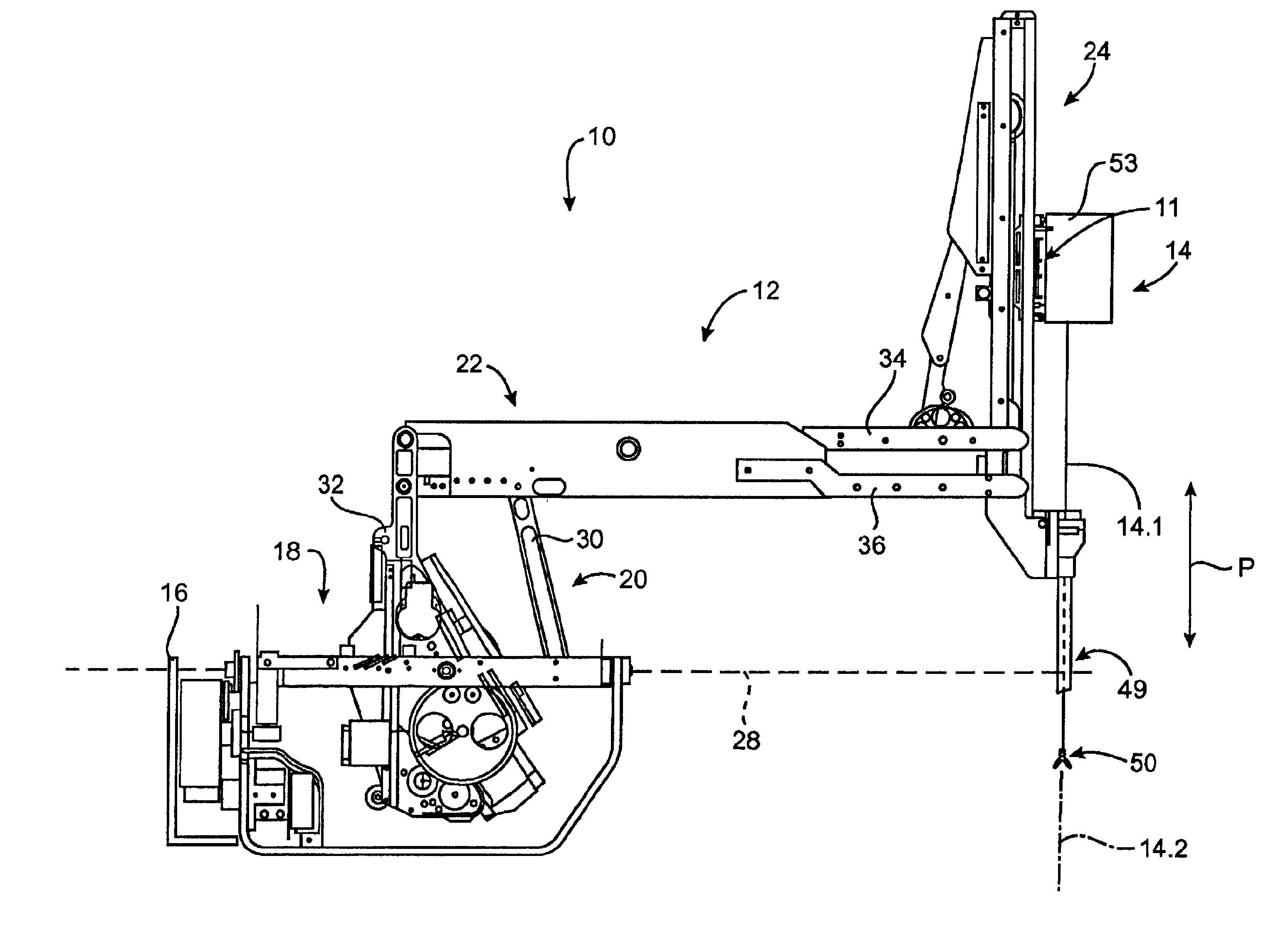
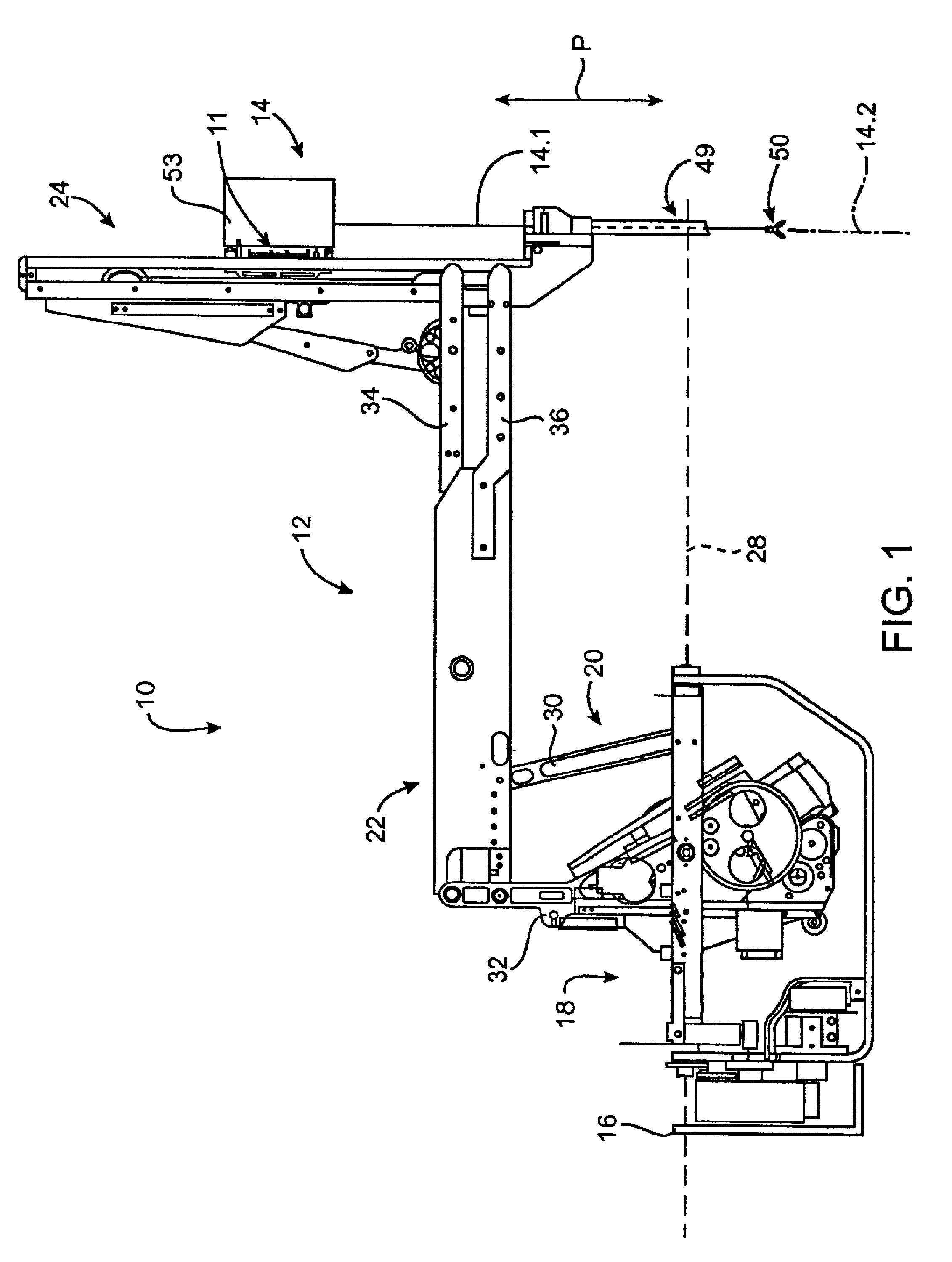
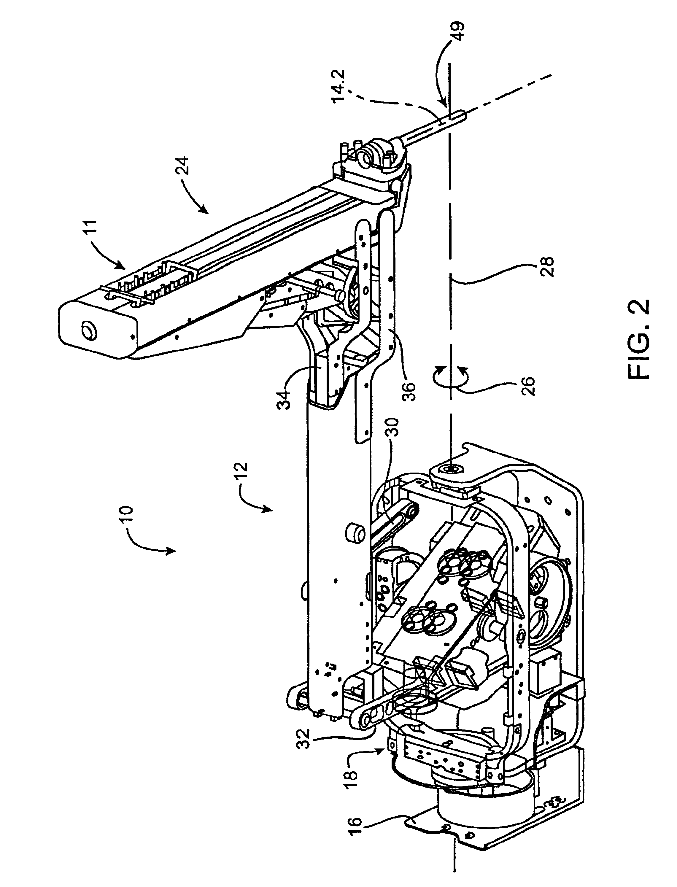
[0051]Referring to FIGS. 1 and 2 of the drawings, a robotic arm and surgical instrument assembly of a preferred embodiment of the invention is generally indicated by reference numeral 10.

[0052]The assembly 10 includes a robotic arm, generally indicated by reference numeral 12. It further includes a surgical instrument schematically and generally indicated by reference numeral 14 in FIG. 1. FIG. 3 indicates the general appearance of the surgical instrument 14.

[0053]The surgical instrument 14 includes an elongate shaft 14.1. A wrist-like mechanism, generally indicated by reference numeral 50, is located at a working end of the shaft 14.1. A housing 53 arranged releasably to couple the instrument 14 to the robotic arm 12, is located at an opposed end of the shaft 14.1. In FIG. 1, and when the instrument 14 is coupled or mounted on the robotic arm 12, the shaft 14.1 extends along an axis indicated at 14.2. The instrument 14 is typically releasably mounted on a carriage 11 that is driven...


PUM


Abstract

This invention provides surgical tools or instruments for use in minimally invasive telesurgical applications. The instruments typically include a base whereby the instrument is removably mountable on a robotically controlled articulated arm. An elongate shaft extends from the base. A working end of the shaft is disposed at an end of the shaft remote from the base. A wrist member is pivotally mounted on the working end. At least one end effector element mounting formation is pivotally mounted on an opposed end of the wrist member. A plurality of elongate elements, e.g., cables, extend from the end effector element mounting formation and the wrist member to cause selective angular displacement of the wrist member and end effector mounting formation in response to selective pulling of the elongate elements.

Description

CROSS-REFERENCES TO RELATED APPLICATIONS[0001]This is a divisional application of U.S. patent application Ser. No. 09 / 398,958, filed Sep. 17, 1999 now U.S. Pat. No. 6,394,998, which is a nonprovisional application of U.S. Patent Application Ser. No. 60 / 116,844, filed Jan. 22, 1999, the full disclosures of which are herein incorporated by reference.BACKGROUND OF THE INVENTION[0002]The present application is generally directed to medical devices, systems, and methods. In a particular embodiment, the invention provides telesurgical robotic tools, systems and methods.[0003]Advances in minimally invasive surgical technology could dramatically increase the number of surgeries performed in a minimally invasive manner. Minimally invasive medical techniques are aimed at reducing the amount of extraneous tissue that is damaged during diagnostic or surgical procedures, thereby reducing patient recovery time, discomfort, and deleterious side effects. The average length of a hospital stay for a ...

Claims


Application Information

Patent Timeline
IPC IPC(8): A61B19/00A61B17/00
CPCA61B19/2203A61B17/00234A61B2019/223Y10T74/20335A61B2019/2242A61B2019/2246A61B2017/00477A61B2019/2234A61B34/30A61B34/35A61B34/71A61B2034/305A61B2034/715
Inventor WALLACE, DANIEL T.JULIAN, CHRISTOPHER A.MORLEY, TRACEY A.BARON, DAVID S.
Owner PENN STATE RES FOUND
Why Eureka
Try Eureka