Prosthetic heart valve with slit stent

a heart valve and prosthesis technology, applied in the field of prosthetic heart valves, can solve the problems of shortening the useful life of the prosthetic heart valve, concentrating destructive stresses in those areas, and reducing the maximum diameter of the central lumen through the valv

Inactive Publication Date: 2005-08-30
ST JUDE MEDICAL
View PDF16 Cites 469 Cited by
  • Summary
  • Abstract
  • Description
  • Claims
  • Application Information

AI Technical Summary

Problems solved by technology

However, such suturing has been found to place stress on the material as the valve opens and closes, thus leading to a shorter useful life for the prosthetic heart valve.
In fact, any attachment technique which creates a hole in the tissue near the post tips may concentrate destructive stresses in those areas.
One limitation frequently found in prior art stented valves is that the mechanism which attaches th...

Method used


Image

  • Prosthetic heart valve with slit stent
  • Prosthetic heart valve with slit stent
  • Prosthetic heart valve with slit stent

Examples


Embodiment Construction

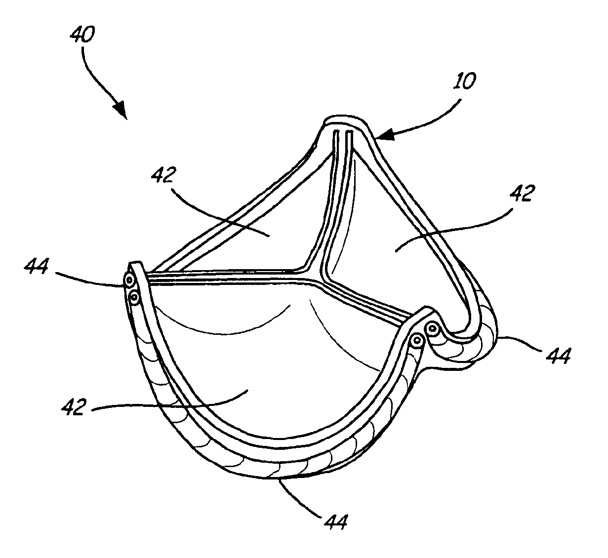
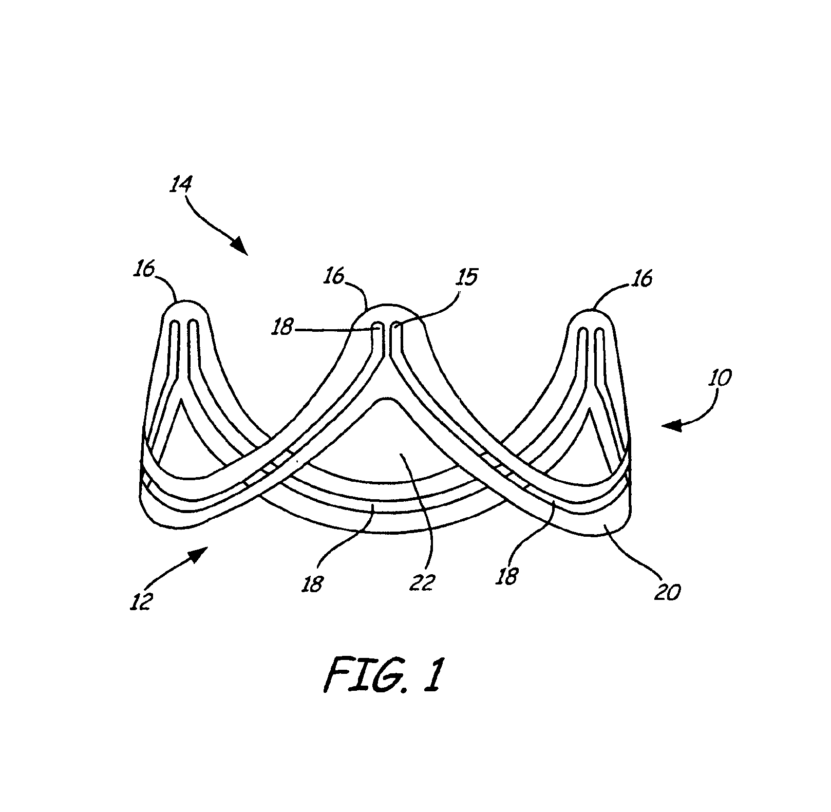
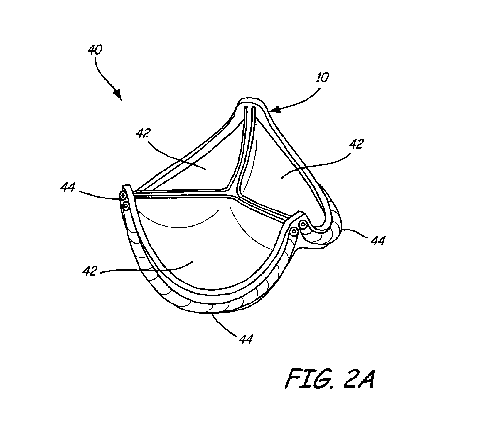
[0016]FIG. 1 is a side plan view of a stent 10 in accordance with the present invention. Stent 10 includes an inflow opening 12, an outflow opening 14 and commissure posts 16 with scallops extending between posts. The shape of stent 10 generally matches the native valve geometry such that the leaflets will coapt properly. As shown in FIG. 1, stent 10 includes slits 18 which extend between posts 16 and from an outer surface 20 to a central lumen 22 through the stent 10. The vertical portion 15 of slits 18 ensure proper coaptation of adjacent leaflets. In general, it is preferable to have vertical slits 15 as close as possible to one another such that there are no gaps between adjacent leaflets, thereby reducing leakage between adjacent leaflets. Slits 18 should be wide enough to just allow the leaflets 42 to pass through. The slits can extend over any length of the stent. In one specific example, they extend about 95%, or more, of the distance to the tip of the commissure. Preferably...


PUM


Abstract

A valve prosthesis includes a plurality of flexible leaflets and a stent having a central lumen. A slit in the stent extends from the central lumen to an outer surface. An occluding portion of the flexible leaflets extends across the central lumen and an attachment portion extends from the central lumen through the slit and forms a sewing cuff for attachment to a patient's tissue. The attachment portion forms a sewing cuff for attachment to native heart tissue.

Description

FIELD OF THE INVENTION[0001]The present invention relates to prosthetic heart valves. More specifically, the present invention relates to attachment of a biocompatible material of a prosthetic heart valve to a native tissue annulus.BACKGROUND OF THE INVENTION[0002]Prosthetic heart valves have been used for replacing damaged or diseased heart valves in patients. Various types of prosthetic heart valves are known, including mechanical heart valves and bioprosthetic heart valves. Bioprosthetic heart valves may include a material, such as tissue or synthetic polymers, carried on a stent. The material typically comprises animal tissue, such as porcine aortic valve material or bovine pericardium.[0003]Different techniques are known for coupling the material to the stent. For example, suturing the valve material to the stent is one common technique. However, such suturing has been found to place stress on the material as the valve opens and closes, thus leading to a shorter useful life for...

Claims


Application Information

Patent Timeline
IPC IPC(8): A61F2/24
CPCA61F2/2409A61F2/2412
Inventor BUCHANAN, ERIC S.
Owner ST JUDE MEDICAL
Why Eureka
Try Eureka