Triggerless welding implement and method of operating same

a technology of welding implement and trigger, which is applied in the field of triggerless welding assembly, system and method, can solve the problems of increasing the time and cost of assembling and operating the welding implement, prone to failure of devices, and user fatigue of holding the trigger against the spring bias

Inactive Publication Date: 2005-08-30
ILLINOIS TOOL WORKS INC
View PDF17 Cites 19 Cited by
  • Summary
  • Abstract
  • Description
  • Claims
  • Application Information

AI Technical Summary

Benefits of technology

[0008]According to yet another aspect of the present technique, a method for operating a welding system is featured. The method may comprise disposing a magnet proximate to a welding implement to actuate electrical connectors disposed within the welding implement, thereby controlling operation of the welding system.

Problems solved by technology

After time, a user may become tired of holding the trigger against the spring bias.
However, the installation of the trigger and trigger lock increases the time and cost of assembling and operating the welding implement.
In addition, these devices are susceptible to failure from wear, requiring replacement.

Method used


Image

  • Triggerless welding implement and method of operating same
  • Triggerless welding implement and method of operating same
  • Triggerless welding implement and method of operating same

Examples


Embodiment Construction

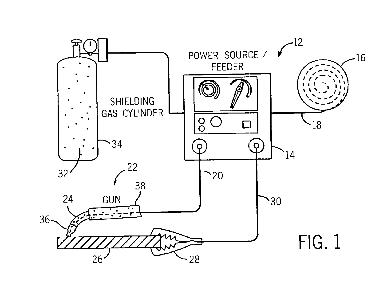
[0022]Referring generally to FIG. 1, this figure depicts an exemplary portable MIG arc welding system 12. However, the present techniques are applicable to other types of arc welding systems, such as fixed systems and submerged arc welding systems. The illustrated embodiment includes a power source / wire feeder 14 having a wire spool 16. The power source / wire feeder 14 accepts an electrode wire 18 from the wire spool 16 and directs the electrode wire 18 into a welding cable 20 of a welding gun 22. However, the present techniques are applicable to welding implements other than a welding gun, such as a robotic welder. In addition, the welding cable 20 is adapted with conductors (not shown) to conduct electric power from the power source / wire feeder 14. In this embodiment, the wire 18 is guided from the welding cable 20 to a neck 24 of the welding gun 22.

[0023]A work piece 26 is electrically coupled to one terminal of the power source / wire feeder 14 by a ground clamp 28 and a ground cab...


PUM

PropertyMeasurementUnit
magnetic fieldaaaaaaaaaa
electricalaaaaaaaaaa
flexibleaaaaaaaaaa

Abstract

A magnetically-actuated switch adapted to control a welding device. The magnetically-actuated switch may comprise a set of electrical connectors that are brought into electrical communication with one another by magnetic force. The magnetically-actuated switch may be disposed within a welding implement coupled to the welding device. The welding implement may be operated by disposing a magnet proximate to the welding implement to actuate the magnetically-actuated switch. The magnet may be disposed within a magnet holder securable to a hand.

Description

FIELD OF THE INVENTION[0001]The present technique system relates to welding systems, and more particularly to a triggerless welding assembly, system, and method.BACKGROUND OF THE INVENTION[0002]Welding is a method that may be used to either join pieces of metal or separate them apart. An exemplary type of welding process is arc welding. An arc welding system typically comprises an electrical power source coupled to a welding implement. An electrode is routed through the welding implement and is electrically coupled to the electrical power source. Additionally, a conductive cable is clamped to a work piece and routed back to the electrical power source. An electric arc is produced between the electrode and the work piece when the electrode is brought into close proximity to, or in contact with, the work piece. The electric current flows from the power source through the electrode to the work piece and back to the electrical power source through the conductive cable. The heat produced...

Claims


Application Information

Patent Timeline
Patent Type & Authority Patents(United States)
IPC IPC(8): A41D19/015H01H9/06H01H36/00
CPCA41D19/01529H01H9/06H01H36/002H01H36/0066
Inventor HANZEL, DANIEL J.
Owner ILLINOIS TOOL WORKS INC
Why Eureka
Try Eureka