Micro-actuator utilizing electrostatic and Lorentz forces, and micro-actuator device, optical switch and optical switch array using the same

a micro-actuator and electrostatic force technology, applied in the direction of instruments, television systems, and semiconductor/solid-state device details, can solve problems such as power consumption, achieve the effects of reducing power consumption, sacrificing small size, and broadening the mobility range of movable parts

Inactive Publication Date: 2005-08-30
NIKON CORP
View PDF9 Cites 14 Cited by
  • Summary
  • Abstract
  • Description
  • Claims
  • Application Information

AI Technical Summary

Benefits of technology

[0018]The present invention was devised in order to solve such problems. The object of the present invention is to provide a microactuator, microactuator device, optical switch and optical switch array which can broaden the mobility range of the movable part and reduce the power consumption without applying a high voltage or sacrificing small size.

Problems solved by technology

In the case of driving by an electrostatic force, since the charging-discharging of a capacitor is performed electrically, power consumption occurs only during charging and discharging, i.e., at points in time at which there is a change in the voltage.

Method used


Image

  • Micro-actuator utilizing electrostatic and Lorentz forces, and micro-actuator device, optical switch and optical switch array using the same
  • Micro-actuator utilizing electrostatic and Lorentz forces, and micro-actuator device, optical switch and optical switch array using the same
  • Micro-actuator utilizing electrostatic and Lorentz forces, and micro-actuator device, optical switch and optical switch array using the same

Examples


Embodiment Construction

[0073]Microactuators constituting working configurations of the present invention, as well as microactuator devices, optical switches and optical switch arrays using these microactuators, will be described below with reference to the figures.

First Working Configuration

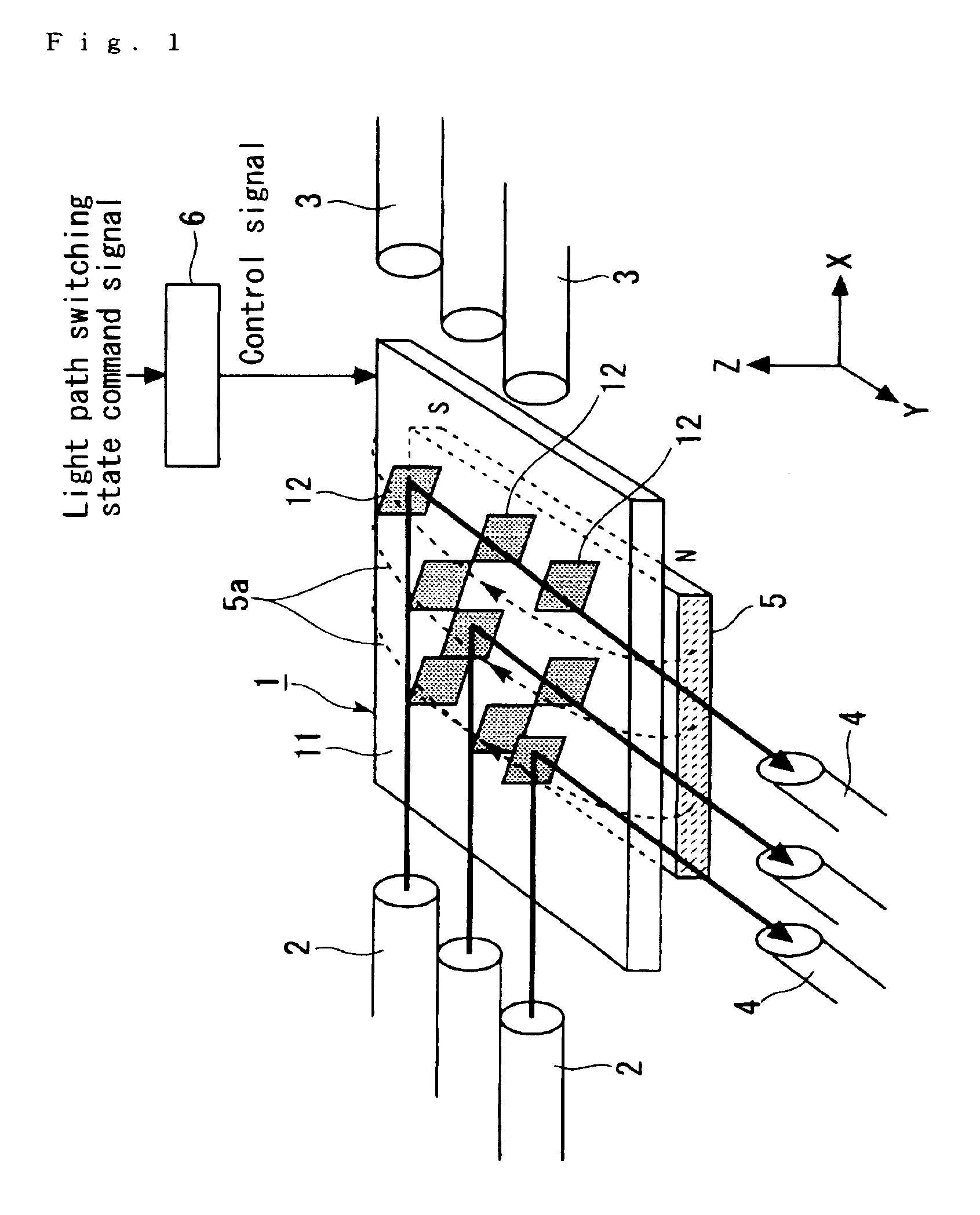
[0074]FIG. 1 is a schematic structural diagram which shows one example of an optical switch system comprising an optical switch array 1 that constitutes a first working configuration of the present invention. For convenience of description, X, Y and Z axes that are mutually perpendicular are defined as shown in FIG. 1 (the same is true of figures described later). The surface of the substrate 11 of the optical switch array 1 is parallel to the XY plane. Furthermore, for convenience of description, the + side in the direction of the Z axis is referred to as the upper side, and the − side in the direction of the Z axis is referred to as the lower side.

[0075]As is shown in FIG. 1, this optical switch system comprises an o...


PUM


Abstract

The movable part 21 is fastened to the substrate 11 via flexure parts 27a and 27b, and can move upward and downward with respect to the substrate 11. The substrate 11 also serves as a fixed electrode. The movable part 21 has second electrode parts 23a and 23b which can generate an electrostatic force between these electrode parts and the substrate 11 by means of a voltage that is applied across these electrode parts and the substrate 11, and a current path 25 which is disposed in a magnetic field, and which generates a Lorentz force when a current is passed through this current path. A mirror 12 which advances into and withdraws from the light path is disposed on the movable part 21. As a result, the mobility range of the movable part can be broadened, and the power consumption can be reduced, without applying a high voltage or sacrificing small size.

Description

[0001]The present application is a continuation of PCT International Application No. PCT / JP02 / 09023 filed Sep. 5, 2002, which is hereby incorporated by reference.TECHNICAL FIELD[0002]The present invention relates to a microactuator, a microactuator device, an optical switch and an optical switch array.BACKGROUND ART[0003]As advances have been made in micro-machining techniques, the need for microactuators has increased in various fields. Optical switches which switch light paths utilized in optical communications, etc., may be cited as one example of a field in which microactuators are used. For instance, the optical switch disclosed in Japanese Patent Application Kokai No. 2001-42233 may be cited as one example of such an optical switch.[0004]Microactuators generally have a fixed part, and a movable part that can be moved by a specified force, and are held in a specified position by the above-mentioned specified force. In conventional microactuators, an electrostatic force is often...

Claims


Application Information

Patent Timeline
Patent Type & Authority Patents(United States)
IPC IPC(8): B81B3/00G02B6/35G02B6/12H04Q11/00G02B26/08B81B7/02
CPCB81B3/0037G02B6/358B81B2201/045B81B2203/0109B81B2203/053G02B6/3514G02B6/3546G02B6/357G02B6/3572G02B6/3584G02B2006/12104G02B26/08
Inventor AKAGAWA, KEIICHISUZUKI, JUNJIISHIZUYA, TOHRUSUZUKI, YOSHIHIKO
Owner NIKON CORP
Why Eureka
Try Eureka