Passive ranging techniques in borehole surveying

Active Publication Date: 2005-08-30
SCHLUMBERGER TECH CORP
View PDF43 Cites 31 Cited by
  • Summary
  • Abstract
  • Description
  • Claims
  • Application Information

AI Technical Summary

Benefits of technology

[0010]Exemplary embodiments of the present invention advantageously provide several technical advantages. For example, supplemental reference data may be used to reference from the bottom up for retrospective correction of the well path. It will be understood that when the borehole is initially near vertical, determination of azimuth is likely to be error prone. A small change in angle of inclination, e.g., 0.01 degrees, may result in the difference between North and South (i.e., an azimuth change of 180 degrees). Thus supplemental reference data may provide substantial retrospective correction of the well path, especially in near vertical segments. A further technical advantage of the supplemental reference data is that it may be used to check the accuracy of the azimuth data. A still further technical advantage of the supplemental reference data is that it offers an independent, stand alone reference downwards. This independent reference is typically not as prone to cumulative errors as the prior art method described in the '119 paten

Problems solved by technology

It will be understood that when the borehole is initially near

Method used


Image

  • Passive ranging techniques in borehole surveying
  • Passive ranging techniques in borehole surveying
  • Passive ranging techniques in borehole surveying

Examples


Example

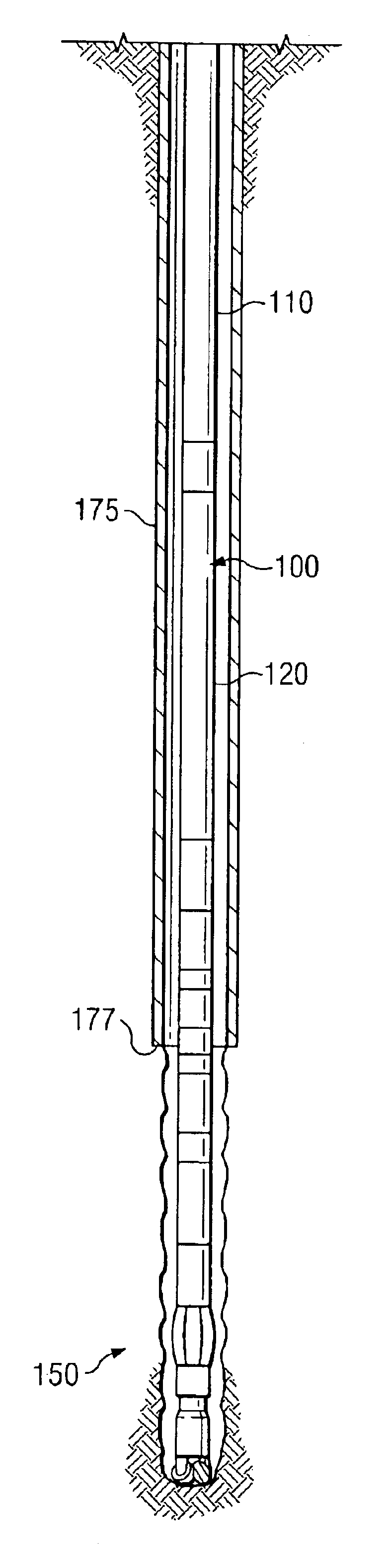
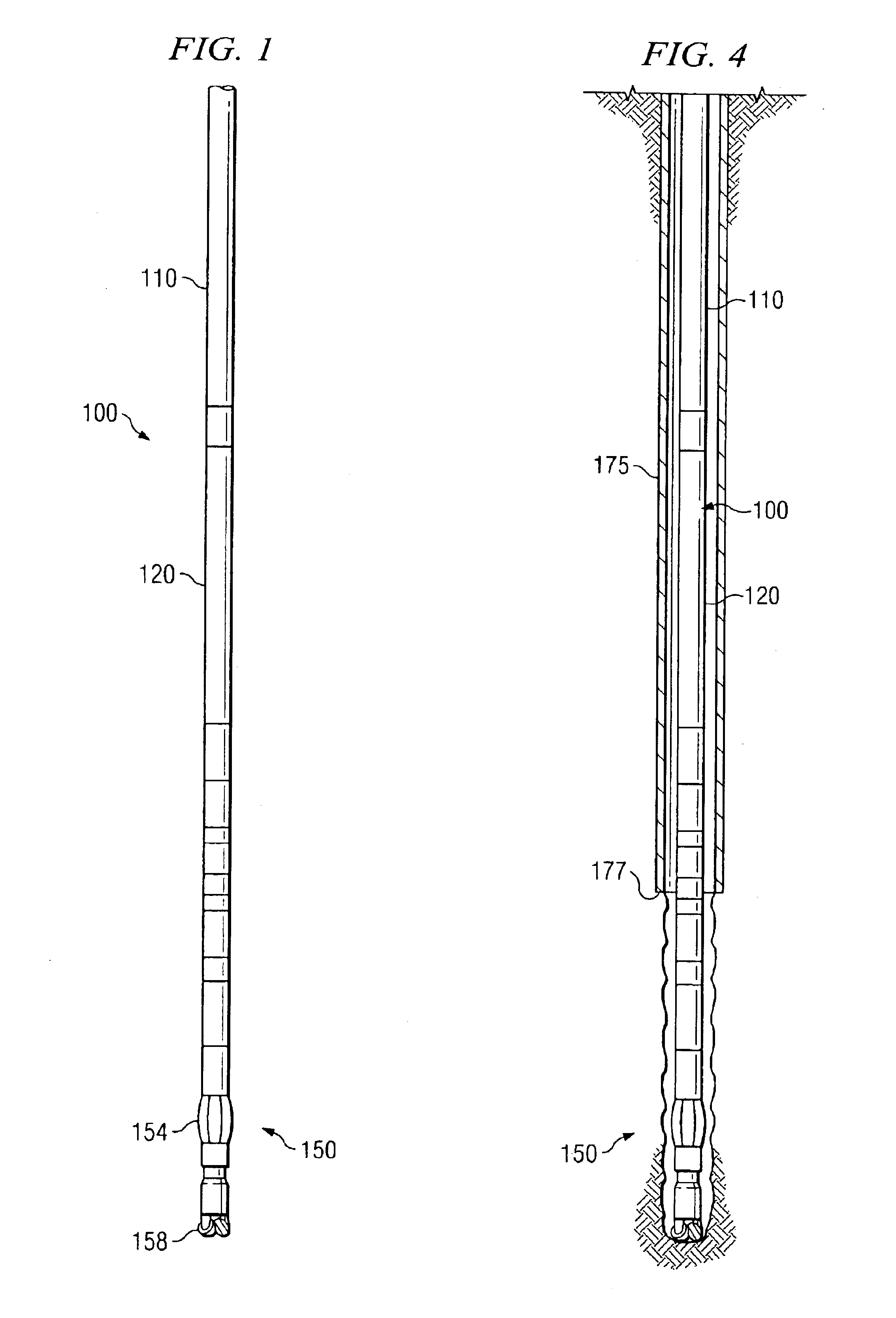
[0029]Referring now to FIG. 1, one exemplary embodiment of a downhole tool 100 according to the present invention is illustrated. In FIG. 1, downhole tool 100 is illustrated as a measurement while drilling (MWD) tool including upper 110 and lower 120 sensor sets coupled to a bottom hole assembly (BHA) 150 including, for example, a steering tool 154 and a drill bit assembly 158. The upper 110 and lower 120 sensor sets are disposed at a known spacing, typically on the order of about 10 to 20 meters (i.e., about 30 to 60 feet). Each sensor set (110 and 120) includes at least two mutually perpendicular gravity sensors, with at least one gravity sensor in each set having a known orientation with respect to the borehole.

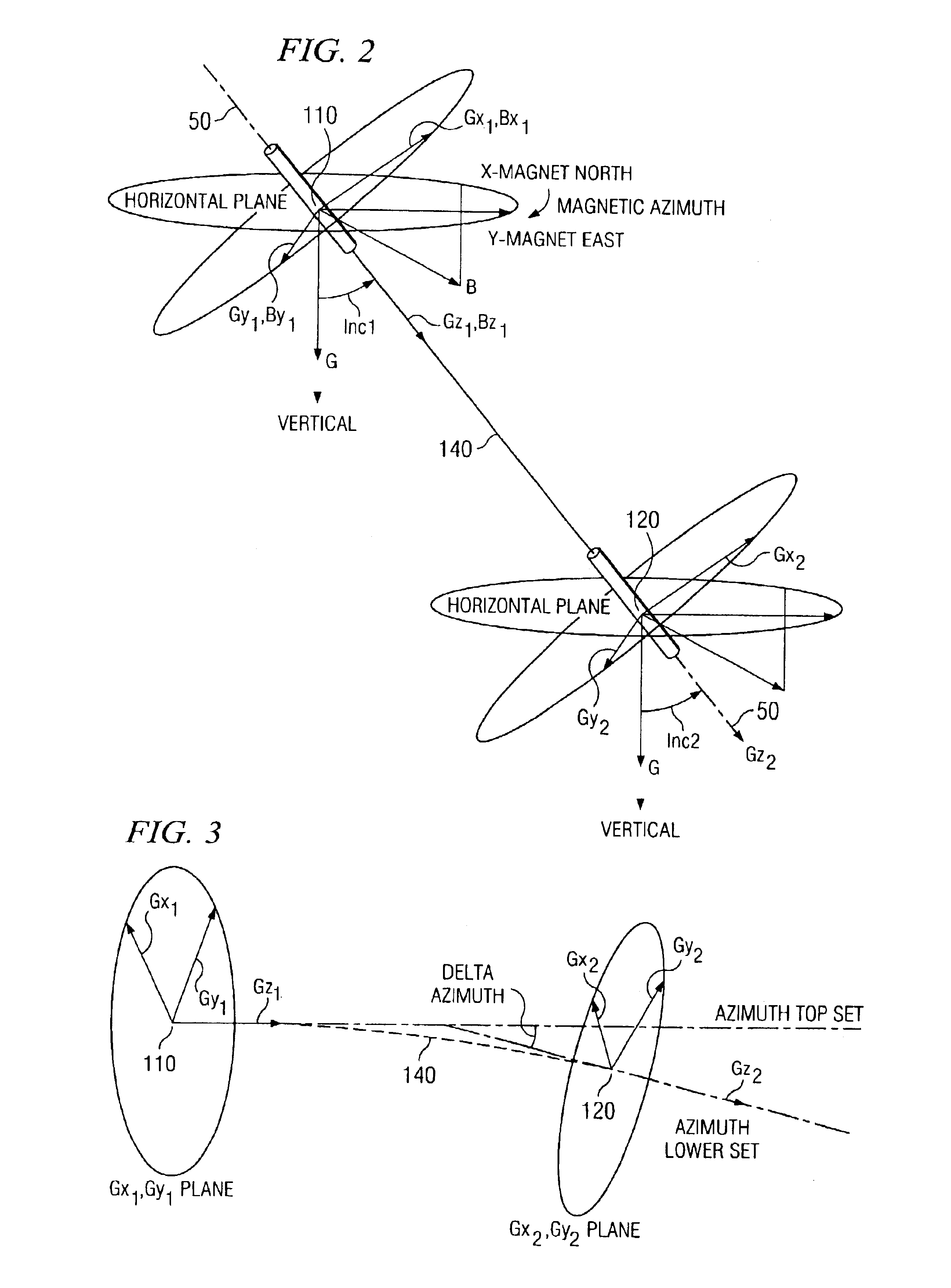
[0030]Referring now to FIG. 2, a diagrammatic representation of a portion of the MWD tool of FIG. 1 is illustrated. In the embodiment shown on FIGS. 1 and 2, each sensor set includes three mutually perpendicular gravity sensors, one of which is oriented substantially paral...


PUM


Abstract

A method for determining the location of a target subterranean structure from within an adjacent borehole is disclosed which uses first and second gravity measurement devices disposed at corresponding first and second positions in the adjacent borehole and a magnetic field measurement device disposed one of the first and second positions. The method includes processing a total local magnetic field, a reference magnetic field, and a local azimuth determined using the gravity measurement devices to determine a portion of the total magnetic field attributable to the subterranean structure multiple points in the adjacent borehole. The location of the subterranean structure is determined using the portion of the total magnetic field attributable thereto. A system adapted to execute the disclosed method and a computer system including computer-readable logic configured to instruct a processor to execute the disclosed method are also provided.

Description

RELATED APPLICATIONS[0001]None.FIELD OF THE INVENTION[0002]The present invention relates generally to surveying a subterranean borehole to determine, for example, the path of the borehole, and more particularly to deployment of primary sensors, such as accelerometers, whose performance in borehole surveying is enhanced by supplemental information from a secondary sensor, such as a magnetometer.BACKGROUND OF THE INVENTION[0003]The use of accelerometers in prior art subterranean surveying techniques for determining the direction of the earth's gravitation field at a particular point is well known. The use of magnetometers or gyroscopes in combination with one or more accelerometers to determine direction is also known. Deployments of such sensor sets are well known to determine borehole characteristics such as inclination, azimuth, positions in space, tool face rotation, magnetic tool face, and magnetic azimuth (i.e., an azimuth value determined from magnetic field measurements). Whil...

Claims


Application Information

Patent Timeline
IPC IPC(8): G01V7/00G01V3/18G01V3/26
CPCG01V3/26G01V7/00E21B47/022G01V3/08G01V11/00
Inventor MCELHINNEY, GRAHAM
Owner SCHLUMBERGER TECH CORP
Why Eureka
Try Eureka