Liquid crystal display method and liquid crystal display device improving motion picture display grade

a liquid crystal display and liquid crystal technology, applied in the field of liquid crystal display methods and liquid crystal display devices, can solve the problems of complex circuitry, deterioration of display grade, and afterimages that may be seen in motion picture displays

Inactive Publication Date: 2005-08-30
SHARP KK
View PDF14 Cites 101 Cited by
  • Summary
  • Abstract
  • Description
  • Claims
  • Application Information

AI Technical Summary

Problems solved by technology

In the conventional active matrix type LCD device as described above, since the response speed of liquid crystals, particularly response speed among halftones, is slower than 16.7 ms, which is the one-frame period, there has been a problem of display grade deterioration that afterimages may be seen in motion picture display.
As a result, the display grade deteriorates as another problem.
However, the liquid crystal display method disclosed in Reference 2 has the following problem.
As a result, the circuitry is complicated, leading to a cost increase, as a problem.
The liquid crystal display method disclosed in Referen

Method used


Image

  • Liquid crystal display method and liquid crystal display device improving motion picture display grade
  • Liquid crystal display method and liquid crystal display device improving motion picture display grade
  • Liquid crystal display method and liquid crystal display device improving motion picture display grade

Examples


first embodiment

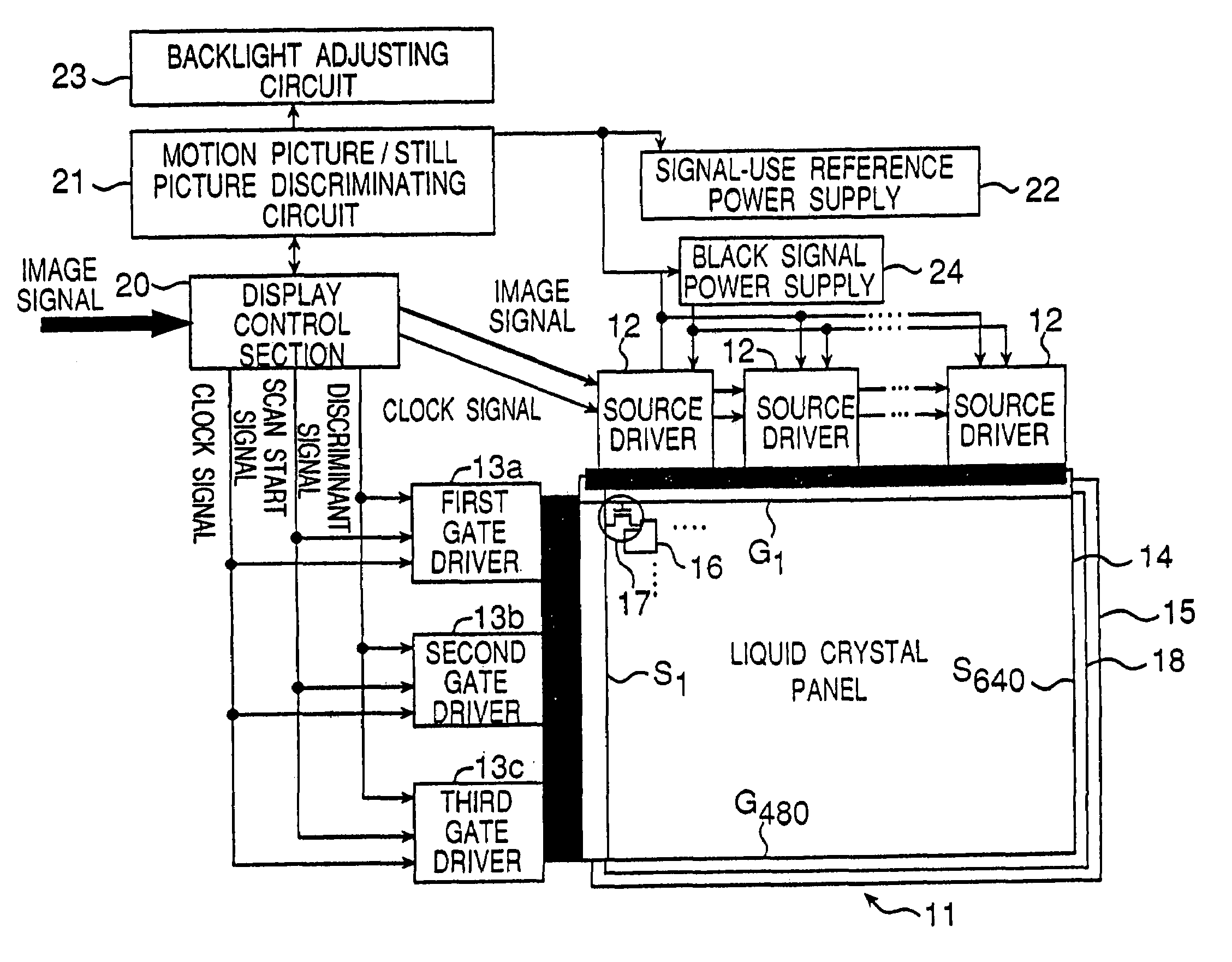
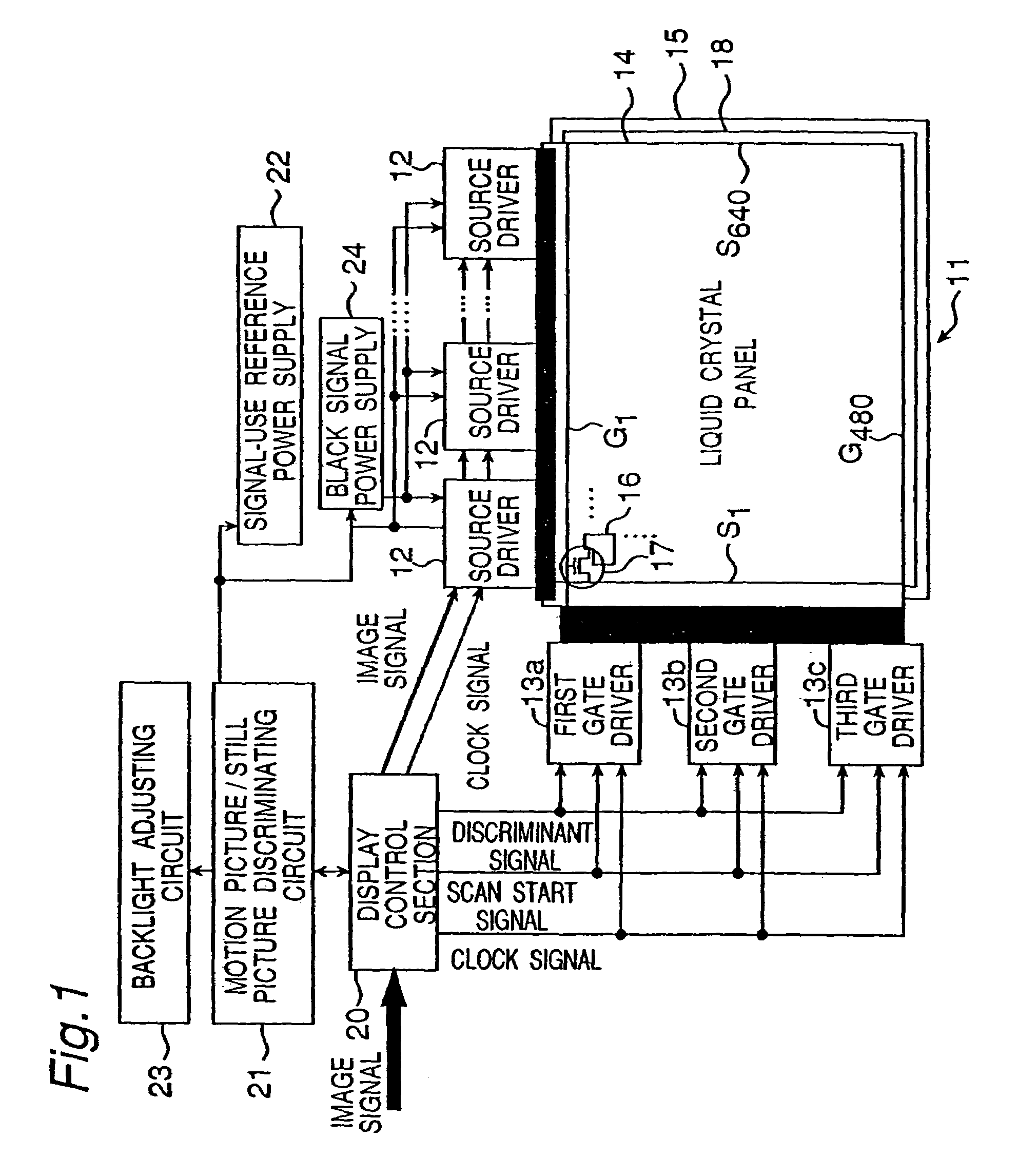
[0139]FIG. 1 is a schematic block diagram of an active matrix type LCD device as an LCD device of this embodiment. The LCD device of this embodiment has a liquid crystal panel 11, a plurality of source drivers 12 and a plurality of gate drivers 13. The liquid crystal panel 11 has a TFT substrate 14 and a counter substrate 15. On the TFT substrate 14, are formed pixel electrodes 16 arrayed in a matrix shape, TFTs 17 the drains of which are connected to the pixel electrodes 16, gate lines G connected commonly to gates of the TFTs 17 of each row and arrayed in parallel, and source lines S connected commonly to sources of the TFTs 17 of each column and arrayed in parallel. On the counter substrate 15 opposed to the TFT substrate 14 with a specified spacing, counter electrodes 18 are formed opposite to the pixel electrodes 16. Also, although not shown, liquid crystals are sandwiched between the pixel electrodes 16 and the counter electrodes 18.

[0140]The liquid crystal panel 11 of this em...

second embodiment

[0190]The LCD device in this embodiment is similar in general configuration to the active matrix type LCD device of the first embodiment shown in FIG. 1. However, the LCD device in this embodiment employs the S-XGA (super XGA) panel for the liquid crystal display section. The pixels count 1280 (tripled for color display)×1024, differing from the VGA panel of the first embodiment by about a double in terms of the number of gate lines G. Therefore, as in the first embodiment, if the data signal and the reset signal are alternately outputted with the same output time width, the selection time for one horizontal line is about 16.7 ms (one frame period) / 1024 (lines) / 2≈about 8.1 μs. Thus, enough signal write to the pixels (i.e., charging) cannot be achieved.

[0191]In addition, from the viewpoint of the power of the TFT devices that switch the connection between the particular electrodes and the source lines S, the selection time for one horizontal line is necessarily 12.0 μs at the least. ...

third embodiment

[0207]The LCD device of the first embodiment, when used under low temperatures, become lower in the response speed of liquid crystals, so that the data signal for the succeeding frame is written before the black display by the reset signal is completed. As a result, there is a problem that the amount of blurs of motion pictures is increased. Whereas this problem can be solved by applying the second embodiment, i.e., by switching the discriminant signal from the display control section 20, the problem can also be solved by controlling the response time which elapses while the transmissivity changes from one corresponding to the data signal to another corresponding to black, so that the response time falls within the frame period. Below described is a method for controlling the response time that elapses while the transmissivity changes from an arbitrary one corresponding to the data signal to another corresponding to black.

[0208]The following response time control methods are availab...


PUM


Abstract

A source driver outputs a data signal and a reset (black) signal alternately to a source line. Four-hundred and eighty gate lines are divided into three groups each comprising 160 lines, and connected to gate drivers. A display control section outputs a discriminant signal, a scan start signal and a clock signal to the gate drivers, where the nth gate line is selected with the data signal outputted by the source driver, and where the (n+160)th gate line is selected with the reset signal outputted. Further, n is shifted sequentially. By writing the reset signal during the latter ⅓ of one frame like this, light leakage of pixels that are changed over from white display to black display is eliminated. Also, blurs of edge portions of a motion picture are reduced. Thus, display grade for motion pictures is enhanced with a minimum improvement.

Description

BACKGROUND OF THE INVENTION[0001]The present invention relates to a liquid crystal display method and a liquid crystal display device which are superior in motion picture display.[0002]Hitherto, there has been available an active matrix type LCD (Liquid Crystal Display) device. In this active matrix type LCD device, as shown in FIG. 31, each time one-horizontal-line data is sampled from an image signal to a sampling memory 2 by a source driver 1, the sampled data is stored into a holding memory 3. On the liquid crystal panel side, a horizontal line made up of a row of pixels into which data is to be written is selected by a gate driver (not shown), and TFTs (Thin Film Transistors) of the selected pixels are turned on. Then, the one-horizontal-line data signal stored in the holding memory 3 is converted from digital to analog form by a D / A converter 4 and written as such via a source line 6 into all the pixels constituting the selected horizontal line.[0003]This operation is executed...

Claims


Application Information

Patent Timeline
IPC IPC(8): G09G3/36G09G3/34G02F1/133G09G3/20H04N5/66
CPCG09G3/3648G09G3/3677G09G3/3688G09G3/2011G09G3/3406G09G2310/0205G09G2310/027G09G2310/0297G09G2310/061G09G2320/0261G09G2320/10G09G2320/103G09G3/36
Inventor MIYACHI, KOICHI
Owner SHARP KK
Why Eureka
Try Eureka