Electronic endoscope selector and electronic endoscope system

a selector and electronic technology, applied in the field of electronic endoscope system, can solve the problems of cumbersome and time-consuming, difficult to decide the correct diagnosis and treatment, etc., and achieve the effect of easy adjustment of video signals

Inactive Publication Date: 2005-08-30
ASAHI KOGAKU KOGYO KK
View PDF9 Cites 59 Cited by
  • Summary
  • Abstract
  • Description
  • Claims
  • Application Information

AI Technical Summary

Benefits of technology

[0009]Therefore, an object of the present invention is to provide an electronic endoscope selector that enables a plurality of electronic endoscope units to share a peripheral device and integrate a plurality of electronic endoscope systems into a single organized electronic endoscope system. Further, the object of the present invention is to provide the electronic endoscope selector, which easily adjusts video signals, so that the color tone of images on the image indicating device appear the same for each electronic endoscope unit.

Problems solved by technology

However, in the above system, the color tones of the images, captured by each electronic endoscope unit, may be dissimilar to each other when displayed on the TV monitor.
Therefore, when the color of a diseased part is an essential factor for a diagnosis, an operator may be confused by the above color tone difference and may have difficulty in deciding the correct diagnosis and treatment, as the operator may not know which image of the electronic endoscope unit should be referred to as the criteria for diagnosis.
The above adjustment for each unit may be carried out by operating respective control panels for each unit, thus it is cumbersome and time consuming.

Method used


Image

  • Electronic endoscope selector and electronic endoscope system
  • Electronic endoscope selector and electronic endoscope system
  • Electronic endoscope selector and electronic endoscope system

Examples


Embodiment Construction

[0021]The present invention is described below with reference to the embodiments shown in the drawings.

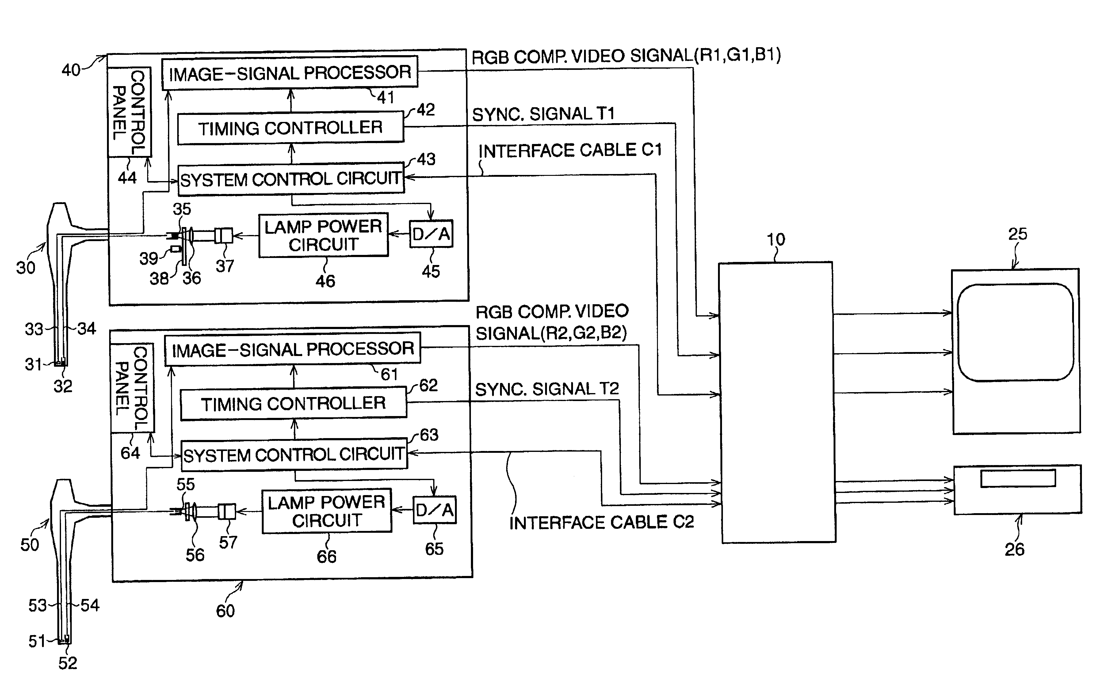
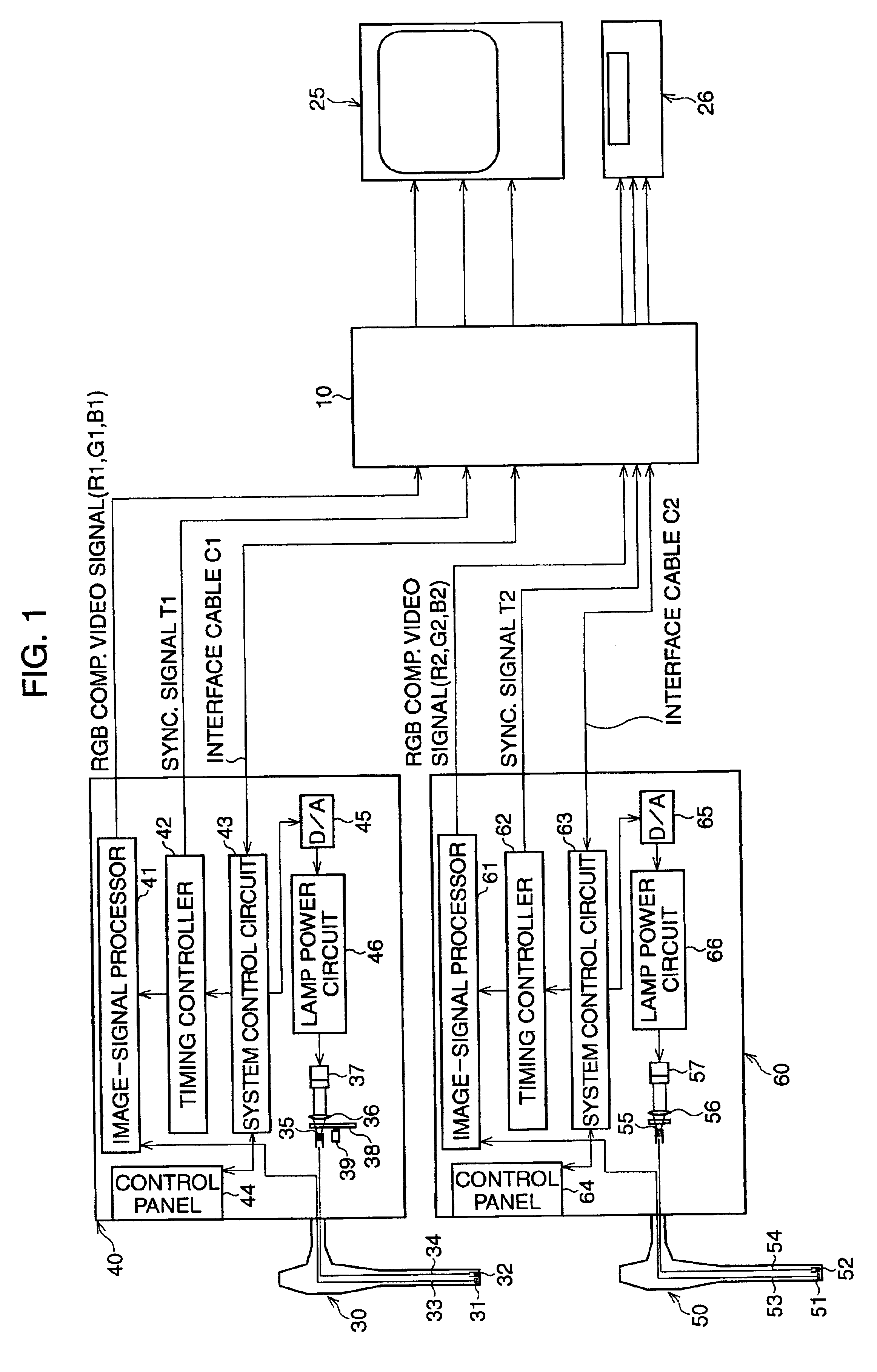
[0022]FIG. 1 is a schematic showing the electrical construction of an electronic endoscope system of the present embodiment and two types of conventional electronic endoscopes utilized in the system.

[0023]The image-signal processing units 40 for a RGB sequential method, the image-signal processing units 60 for a color chip method, the TV monitor 25 and VCR 26, which are shared by the above two processing units, are detachably connected to the electronic endoscope selector 10 via connectors (not shown). An endoscope 30 that conforms to the RGB sequential method is connected to the image-signal processing unit 40 and an endoscope 50 that conforms to the color chip method is connected to the image-signal processing unit 60. Each of the endoscopes 30 and 50 is detachably attached to respective image-signal processing units 40 and 60 by a scope connector (not shown). On the TV monitor 2...


PUM


Abstract

An electronic endoscope selector that is used in an electronic endoscope system which shares peripheral devices, such as a TV monitor, VCR etc., among a plurality of electronic endoscopes. The electronic endoscope selector comprises switching circuits for switching and selecting video signals and synchronization signals fed from one of the plurality of electronic endoscopes. The selector also comprises amplifiers, gamma correction circuits, a system control circuit and memory. The amplifiers and gamma correction circuits are for adjusting gains and gamma correction of RGB video signals fed from the selected electronic endoscope. Parameters for appropriate gains and gamma correction corresponding to each endoscope are stored in the memory. The system control circuit controls the amplifiers and gamma correction circuits in accordance with the parameters that correspond to the selected electronic endoscope.

Description

BACKGROUND OF THE INVENTION[0001]1. Field of the Invention[0002]The present invention relates to an electronic endoscope system, which comprises a plurality of electronic endoscope units and peripheral devices, such as TV monitors or VCR's (video cassette recorder).[0003]2. Description of the Related Art[0004]As to its purpose and faculty, various types of electronic endoscope systems are manufactured and sold by various makers. For example, a narrow bronchoscope, which is mainly utilized for observation and diagnosis, an endoscope for a digestive track, which is thick and includes a channel for surgical treatment, such as forceps, etc. There are also types of endoscopes with an elongated insertion portion which is hard / soft, long / short and so on.[0005]An operator may utilize several types of electronic endoscope systems during a single checkup or medical examination, since each type of electronic endoscope system has an exclusive purpose. In electronic endoscopy, captured images ar...

Claims


Application Information

Patent Timeline
Patent Type & Authority Patents(United States)
IPC IPC(8): A61B1/045H04N7/18A61B1/04G02B23/24H04N5/225H04N9/07H04N9/69H04N9/73
CPCA61B1/00045A61B1/045H04N7/181
Inventor SUGIMOTO, HIDEOKOIKE, MAKOTO
Owner ASAHI KOGAKU KOGYO KK
Why Eureka
Try Eureka