Contacting point damping method between flex circuit and pivot housing

Inactive Publication Date: 2005-08-30
SEAGATE TECH LLC
View PDF15 Cites 17 Cited by
  • Summary
  • Abstract
  • Description
  • Claims
  • Application Information

AI Technical Summary

Benefits of technology

[0009]The present invention is a damping feature on the contact area between the flexible circuit and the pivot housing, reducing the resonance energy transferred from the flexible circuit to the pivot housing. This invention reduces the direct energy transfer from the flexible circuit to the pivot house by applying a damping feature as embodied by damping material on th

Problems solved by technology

Flexible circuit resonance has been a common problem in disc drives for generations of products.
The flexible circuit motion/vibration/resonance can be large enough to cause functional failure for the drive, e.g. the slider is unable to settle out above the commanded track as rapidly as required.
This approach does not control or damp the flex resonance energy transfer at the contacting area between the flexible circuit and pivot h

Method used


Image

  • Contacting point damping method between flex circuit and pivot housing
  • Contacting point damping method between flex circuit and pivot housing
  • Contacting point damping method between flex circuit and pivot housing

Examples


Example

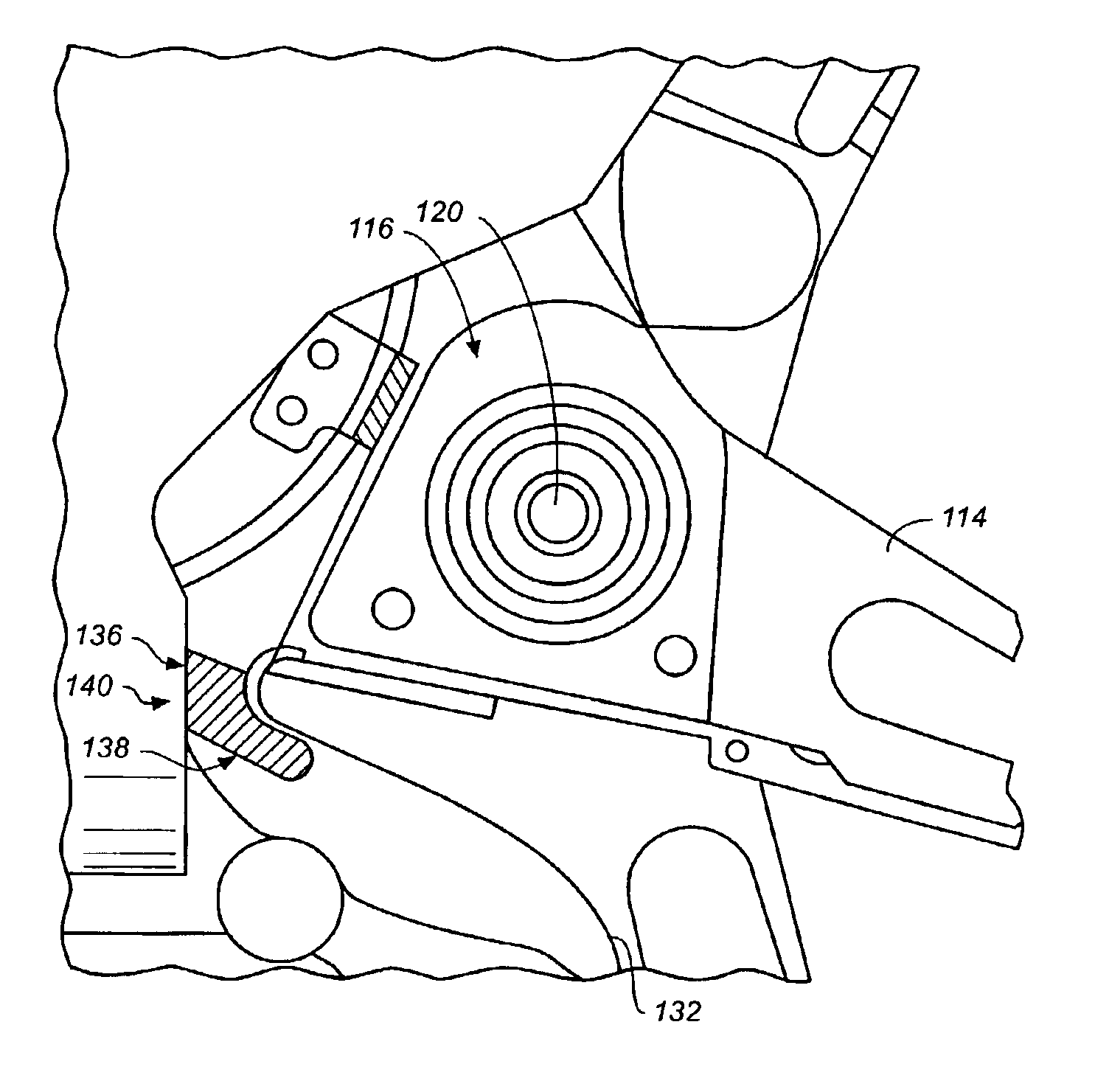
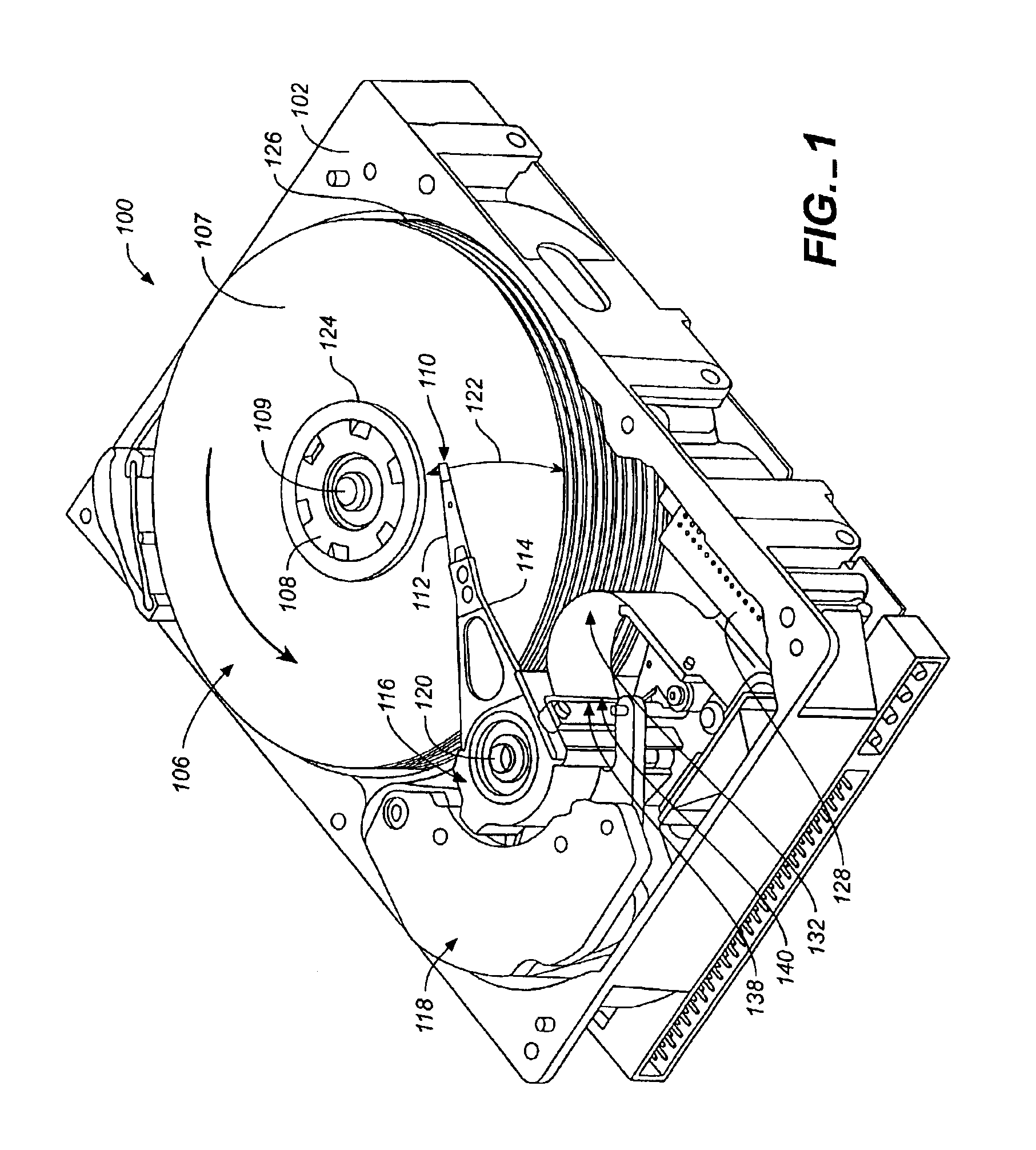
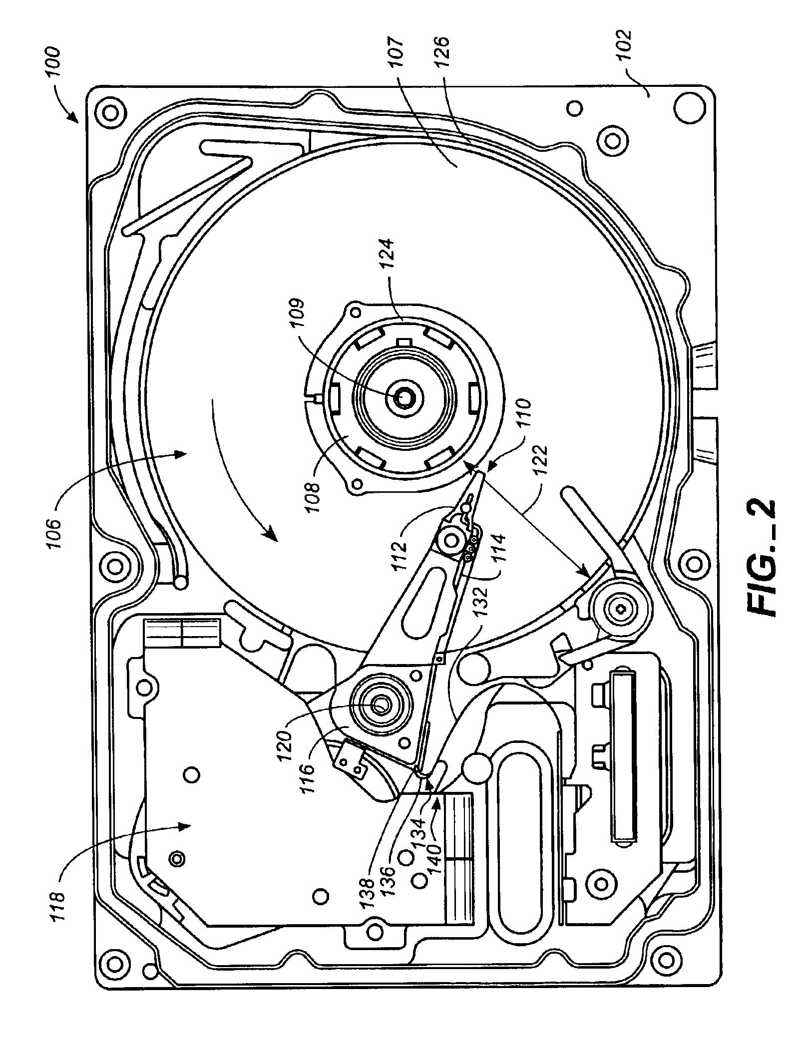
[0023]In a second embodiment, FIG. 4, disc drive 100 has damper 134 disposed on flexible circuit 132 where flexible cable 132 contacts re-routing tip 138. This approach addresses reducing the direct energy transfer from the flex motion to the pivot housing 110 by applying a damping feature directly to existing flexible cable 132 between pivot housing 116 and flexible cable 132. Flex circuit assembly 140 includes flexible cable 132 and damper 134.

Example

[0024]In a third embodiment, FIG. 5, disc drive 100 has re-routing tip comprised of damping material 136. This approach uses damping 136 integrated on the pivot housing 116 to form a flexible re-routing tip 138 and replace the metal re-routing tip 138. This approach addresses reducing the direct energy transfer from the flex motion to the pivot housing 110 by using damping material 136 to form flex re-routing tip 138 between pivot housing 116 and flexible cable 132. This approach differs from the previous two in that a component of disc drive 100, re-routing tip 138, is replaced with a re-routing tip 138 comprised of damping material 136 rather than the existing component simply having damper 134 applied to it. It is believed that this approach works in a similar fashion to re-routing tip 138 covered by damping material 136 as discussed above. Flex circuit assembly 140 includes flexible cable 132 and damping material 136.

[0025]FIGS. 6 and 7 plot Seek Length (x-axis), in numbers of t...


PUM


Abstract

The present invention for a disk drive is a damping feature applied to the contact area between the flexible circuit and the pivot housing, reducing the resonance energy transferred from the flexible circuit to the pivot housing. This invention reduces the direct energy transfer from the flexible circuit to the pivot house by applying a damping feature as embodied by damping material on the flexible circuit or pivot housing at the point at which they make contact or by adding a damper to the flexible circuit re-routing tip area between the pivot housing and the flexible circuit. The damping feature absorbs the resonance energy from the flexible circuit to the damping feature material and reduces the energy transferred from the flexible circuit to the pivot housing.

Description

CROSS-REFERENCE TO RELATED APPLICATION[0001]This application claims priority from U.S. Provisional Application 60 / 352,077 filed on Jan. 24, 2002 for inventors and entitled CONTACTING POINT DAMPING METHOD BETWEEN FLEX CIRCUIT AND PIVOT HOUSING.FIELD OF THE INVENTION[0002]The present invention relates generally to data storage systems, and more particularly but not by limitation to damping contacting components within data storage systems.BACKGROUND OF THE INVENTION[0003]Disc drives are common data storage devices. A typical disc drive includes a rigid housing or deck that encloses a variety of disc drive components. The components include one or more discs having data surfaces coated with a magnetizable medium for storage of digital information in a plurality of circular, concentric data tracks. The discs are mounted on a spindle motor that causes the discs to spin and the data surfaces of the discs to pass under respective hydrodynamic or aerodynamic bearing disc head sliders. The s...

Claims


Application Information

Patent Timeline
IPC IPC(8): G11B5/58G11B5/60
CPCG11B5/58G11B5/60
Inventor ZHAO, LEON LIYANGWANGHAAPALA, KENNETH A.
Owner SEAGATE TECH LLC
Why Eureka
Try Eureka