Scintillating crystal detector

a detector and crystal technology, applied in the field of crystal detectors, can solve the problems of shortening the life time of crucibles or melting furnaces, not easy to manufacture, and high cost, and achieves the effects of reducing non-radiative energy transfer, reducing cost, and increasing stability

Active Publication Date: 2012-04-17
NAT SUN YAT SEN UNIV
View PDF1 Cites 6 Cited by
  • Summary
  • Abstract
  • Description
  • Claims
  • Application Information

AI Technical Summary

Benefits of technology

[0005]The main purpose of the present disclosure is to dope Ca atoms into Ce:LYSO to be charge-compensated with Ce+4 to form Ce+3 for charge balance, where the present disclosure thus obtains high stability with 2 to 10 times greater electrical degree than a general scintillating crystal with a photon yield increased by reducing non-radiative energy transfer reduced yet without charges of Ce atoms changed through annealing.
[0006]The second purpose of the present disclosure is to improve radiative induction to cancer cells with improved energy level of Ce for easily figuring out distribution of the cancer cells.

Problems solved by technology

Although tomography techniques, like computed tomography (CT) and magnetic resonance imaging (MRI), can be used to obtain a sectional image of a tissue, radiative inductions of the tomography techniques are not sensitive to cancer cells and so the cancer cells having abnormal metabolism are not detected at the first time for further preventing the cancer cells from fast divisions.
However, Ce:LSO has a high melting point, which shortens life time of crucible or melting furnace and is not easily fabricated.
Besides, its cost is high.
Yet, lattice of Ce:LYSO is not well arranged and thus has charge defect.
When it is used in PET, its charge defect will make radiation unstable and reduce photon yield owing to non-radiative energy transfer.
As a result, the image obtained does not have high resolution.
Hence, the prior arts do not fulfill all users' requests on actual use.

Method used


Image

  • Scintillating crystal detector
  • Scintillating crystal detector
  • Scintillating crystal detector

Examples


Embodiment Construction

[0011]The following description of the preferred embodiment is provided to understand the features and the structures of the present disclosure.

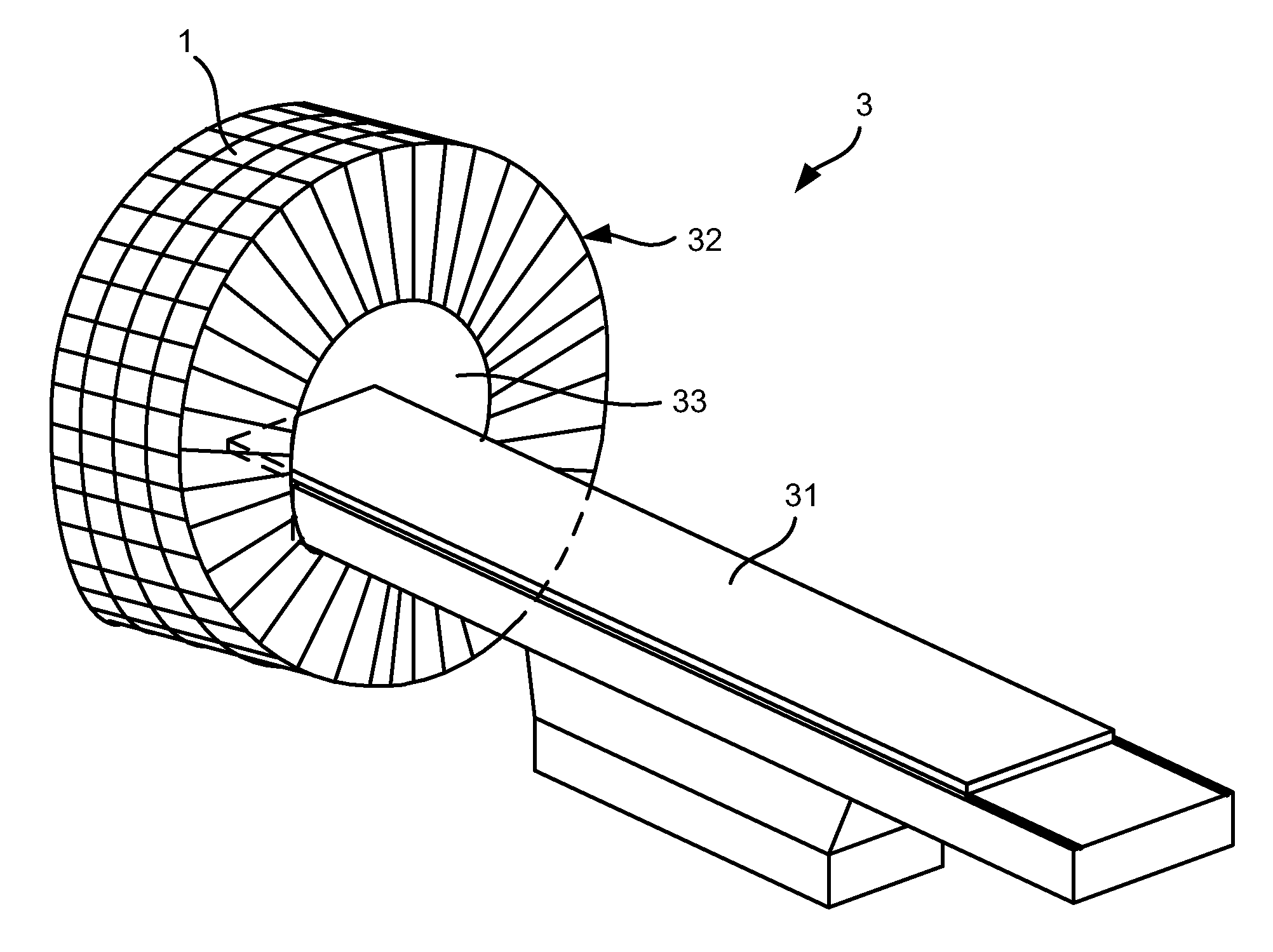
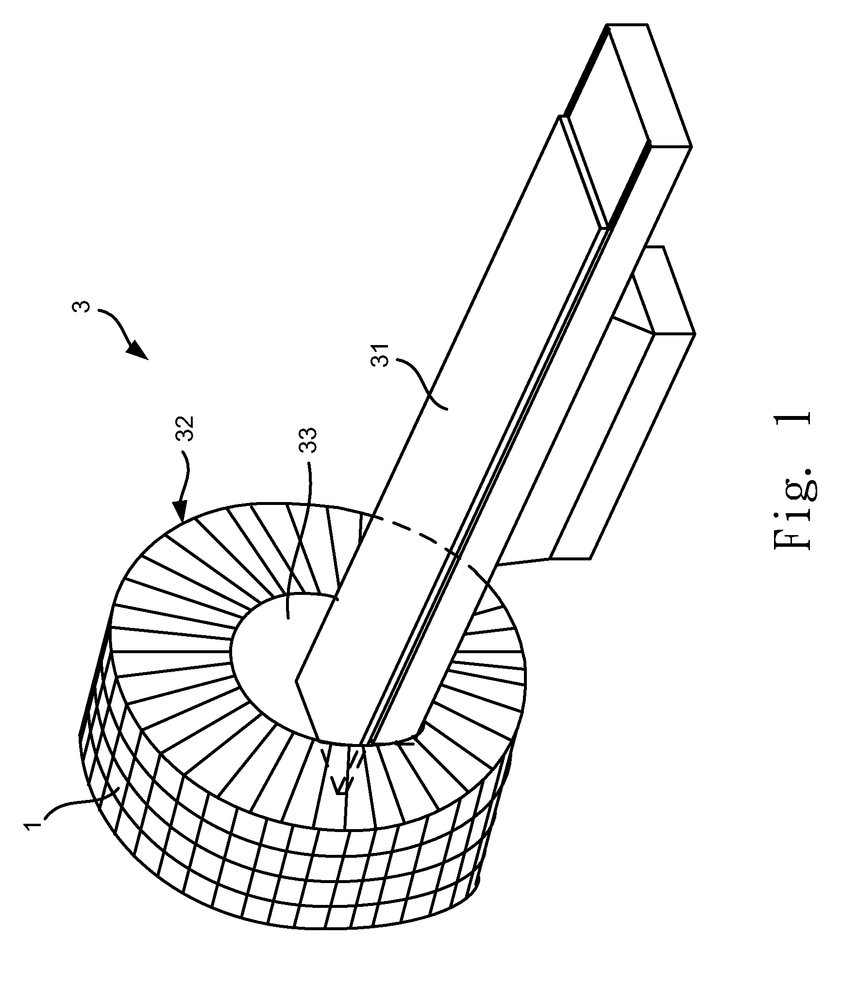
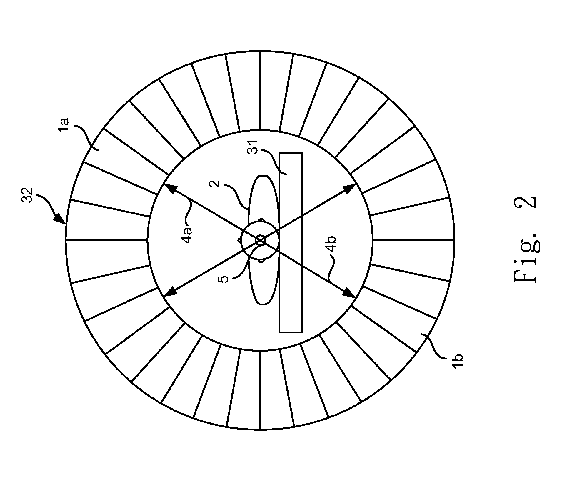
[0012]Please refer to FIG. 1 and FIG. 2, which are a structural view showing a preferred embodiment according to the present disclosure; and a view showing a state of use. As shown in the figures, the present disclosure is a scintillating crystal detector 1, comprising a scintillating crystal structure. The scintillating crystal structure is formed by doping calcium (Ca) atoms into cerium doped lutetium yttrium orthosilicate (Ce:LYSO) for developing cancer cells by the scintillating crystal detector 1. Therein, the Ca atoms are obtained from calcium oxide having a density between 0.00001 and 0.05; and, the scintillating crystal structure can be formed by doping magnesium (Mg) atoms into cerium doped lutetium yttrium orthosilicate (Ce:LYSO). When a to-be-detected object 2 having cancer cells is detected by the scintillating crystal detector 1...


PUM


Abstract

A detector using scintillating crystals is provided. The scintillating crystal is based on cerium doped lutetium yttrium orthosilicate (Ce:LYSO). With calcium (Ca) doped into Ce:LYSO, the electrovalence of Ce is further uniformly distributed. The scintillating crystal obtains high stability with 2 to 10 times greater electrical degree than that of a general scintillating crystal. Thus, radiative induction to cancer cells is improved and distribution of the cancer cells is easily figured out.

Description

TECHNICAL FIELD OF THE DISCLOSURE[0001]The present disclosure relates to scintillating crystal; more particularly, relates to doping calcium (Ca) atoms into cerium doped lutetium yttrium orthosilicate (Ce:LYSO) to be charge-compensated with cerium (Ce) having 4 positive electrovalence (Ce+4) to form Ce having 3 positive electrovalence (Ce+3) for charge balance for improved radiative induction to cancer cells owing to high energy level of Ce.DESCRIPTION OF THE RELATED ARTS[0002]In the modern time, tomography is widely used in clinical and biological fields. It is used to show images of dissected tissues and to observe their physiological functions. Objects of the dissected tissues are laid on a platform to be sent in a tomography machine having a circular cylinder shape for figuring out many 2-dimensional (2D) images of the objects. At last, those 2D images will be used to form 3D images.[0003]Although tomography techniques, like computed tomography (CT) and magnetic resonance imagin...

Claims


Application Information

Patent Timeline
Patent Type & Authority Patents(United States)
IPC IPC(8): G01T1/20
CPCC09K11/7774G21K4/00G01T1/2985A61B6/037C09K11/77742
Inventor CHOU, MITCH M. C.
Owner NAT SUN YAT SEN UNIV
Why Eureka
Try Eureka