Radiant thermal barrier

a technology of radiant barrier and thermal barrier, which is applied in the direction of heat-proofing, mechanical equipment, roofing, etc., can solve the problems of difficult to judge the proper amount of insertion of insulation and the change in effectiveness of radiant barrier, and achieve the effect of convenient installation

Active Publication Date: 2014-07-22
LEWIS DAVID L
View PDF9 Cites 10 Cited by
  • Summary
  • Abstract
  • Description
  • Claims
  • Application Information

AI Technical Summary

Benefits of technology

[0009]It is an object of the invention to provide a radiant thermal barrier that is easy to install and provides a consistent air space without difficulty.
[0010]Another object of the invention is to provide a method for creating a radiant insulating barrier system where low emissivity radiant barrier surfaces of the system are protected from dust and contamination accumulation.
[0011]Still another object is to allow for the addition of multiple layers of reflective insulation layers in order to enhance the thermal efficiency of the system where the additional interior layers of radiant barriers are protected from detrimental surface contamination.
[0012]Yet another object of the invention is to reduce negative conductive energy transfer via framing components.
[0014]In further accord with the first aspect of the present invention, the extended length of board formed for assembly into an enclosure for containing a thermal radiation barrier and for providing protection from accumulation of dust on the thermal radiation barrier. The contained thermal barrier may include a reflective surface on an outside face of the contained thermal barrier for facing the floor, wall, roof, or ceiling from outside the enclosure.
[0021]In further accord with the third aspect of the invention, the insulating material may further comprises a hat cover for forming an enclosed space along with the hat top side and the hat sides for enclosing insulating material within the enclosed space for providing an additional thermal barrier to thermal energy. The insulating material may have a reflective surface facing the hat top side for reflecting thermal energy radiated from the floor, wall, ceiling, or roof and protected from accumulation of dust by enclosure within the enclosed space.

Problems solved by technology

A problem with this method of installation of a radiant reflective barrier, particularly for heated floors, is that it is not easy to judge the proper amount of insertion of the insulation so as to maintain at least three-quarters to one inch of air space needed to create a proper air cavity between a pipe attached to the underside of the floor and the reflective foil lying on top of the fiberglass batting below.
A similar problem exists between studs in forming an air cavity for the same or any similar purpose for a wall or a ceiling or for forming a cavity between roof joists and an attic even if they are not heated.
Moreover, the effectiveness of radiant barriers changes as a result of dust and contamination accumulation on its surfaces.

Method used


Image

  • Radiant thermal barrier
  • Radiant thermal barrier
  • Radiant thermal barrier

Examples


Embodiment Construction

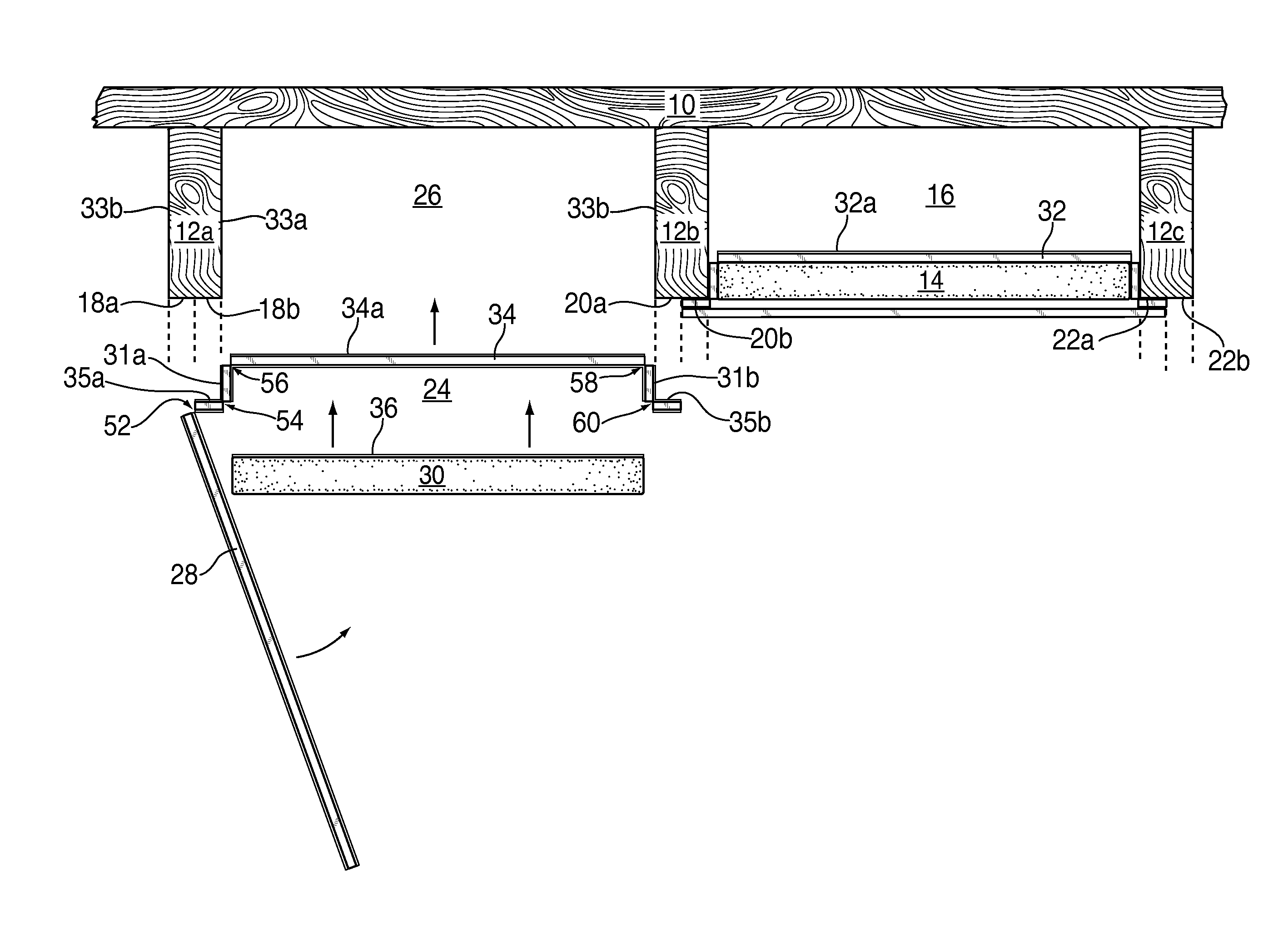
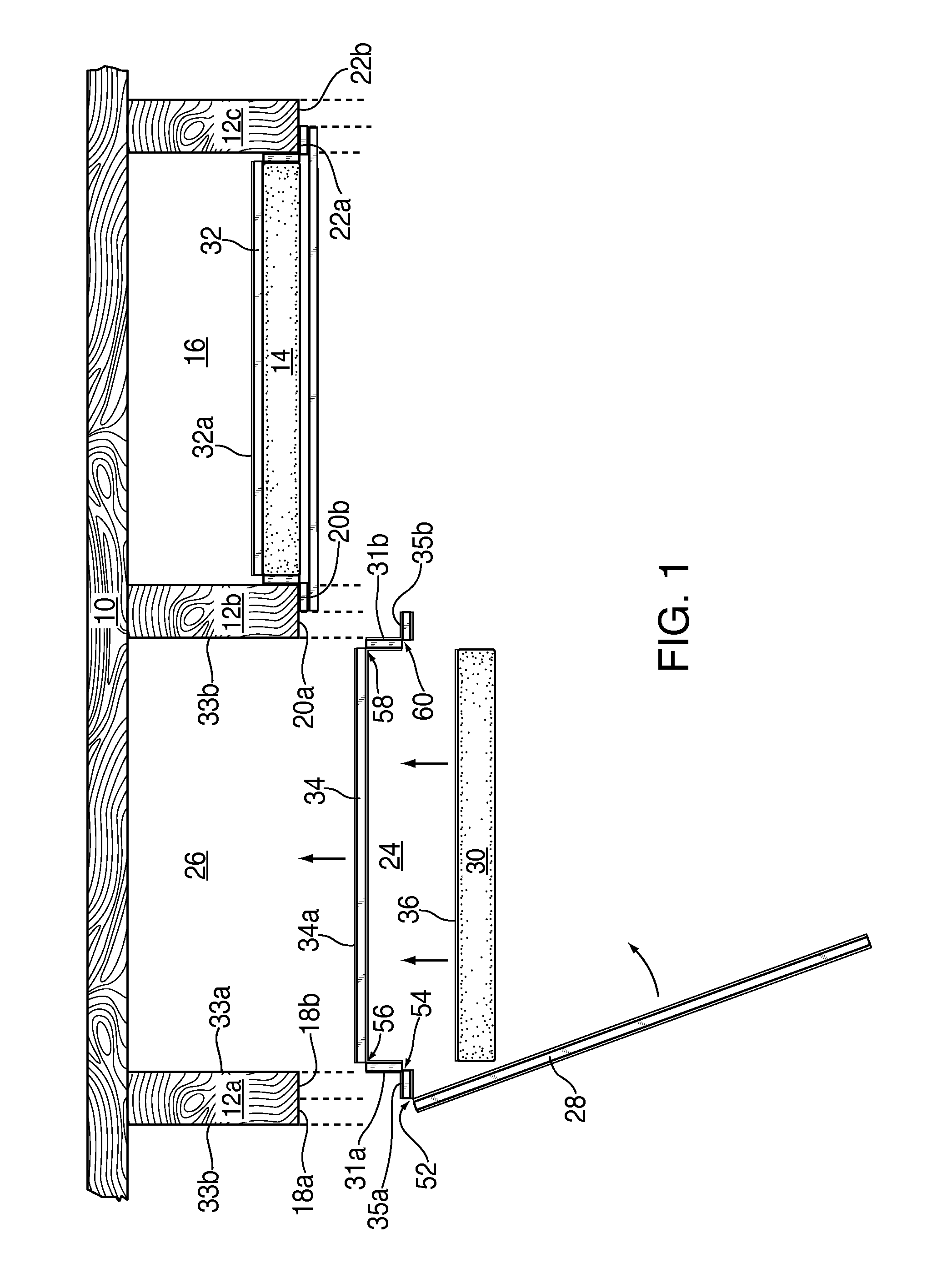
[0028]Reference numeral 10 of FIG. 1 shows a sectional view of a floor, ceiling, wall, or roof of a building supported by a plurality of joists 12a, 12b, 12c.

[0029]A hat-shaped thermal barrier assembly 14 is shown inserted as a barrier to thermal radiation from e.g. above the floor 10 and conducted through the floor into a space 16 between these joists or studs 12b, 12c in such a way that the thermal barrier assembly completely covers the space 16 while also covering a half portion 20b, 22a of edge faces of the joists or studs 12b, 12c. Each edge face comprises two half portions 20a, 20b extending longitudinally along the length of the edge face of the joist, i.e., in a direction perpendicular to the drawing sheet.

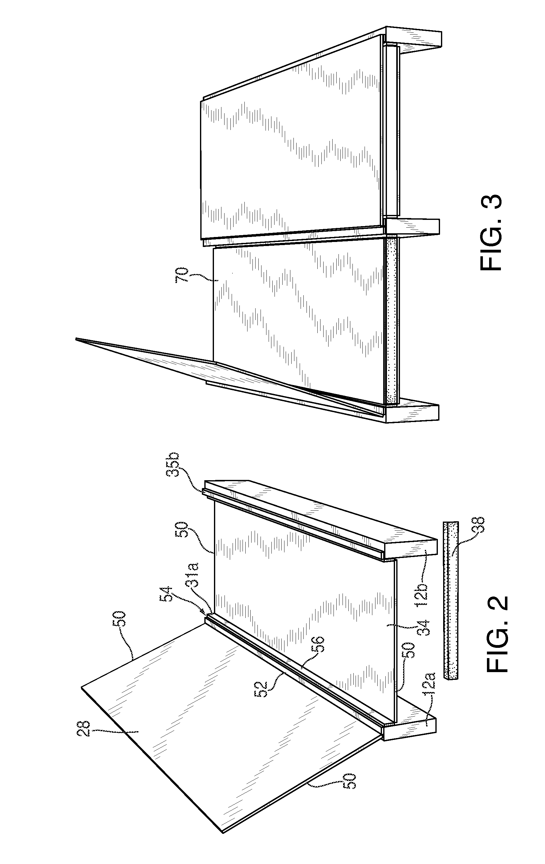
[0030]On the left hand side of FIG. 1 a thermal barrier assembly 24 is shown during the assembly process, after having been folded into the shape shown from an extended length of board (see FIG. 5), which has been previously unfolded, and cut to length for such assembly a...


PUM


Abstract

A thermal barrier is formed into a hat-shape by folding sections of an extended length of board formed for assembly and insertion as a barrier to thermal radiation into a space between two joists or studs of a floor, wall, roof, or ceiling of a building for completely covering the space while also covering protruding edges of the joists or studs so as to reduce thermal energy transfer through the joists or studs themselves. A thermal barrier assembly is shown with an outer reflective surface and is also shown for assembly into a form having an inner enclosure for enclosing an inner thermal barrier also having a reflective surface for reducing thermal radiation transfer by reflection and protected from dust by virtue of the enclosure.

Description

BACKGROUND OF THE INVENTION[0001]The present invention relates to a thermal transfer barrier and, more particularly, for use in construction to help control energy flow into and out of homes and buildings.[0002]Heat transfer through building structures occurs through convection conduction and radiation. In order to retard heat flow by conduction and convection, exterior walls and roofs are built with interior walls, floors, and ceilings having internal air spaces in between. Conduction and convection through the air spaces combined represents only 20 to 35 percent of the heat which passes through them. In both winter and summer 65 to 80 percent of the heat that passes from a warm wall to a colder wall or through a ventilated attic does so by radiation.[0003]Radiant barrier materials may be formed of aluminum foil laminates in which the foil is laminated to kraft paper, cardboard, plastic films or to OSB / plywood roof sheathing. Another variation is aluminized plastic films comprising...

Claims


Application Information

Patent Timeline
Patent Type & Authority Patents(United States)
IPC IPC(8): E04B1/74
CPCE04B1/7654F16L59/02E04D13/1625E04B2001/7691F16L59/08E04B1/62E04B1/76
Inventor LEWIS, DAVID, L.
Owner LEWIS DAVID L
Why Eureka
Try Eureka