Exhaust heat recovery system
a heat recovery system and exhaust heat technology, applied in the direction of machines/engines, lighting and heating apparatus, heating types, etc., can solve the problem of small loss of heat energy, and achieve the effect of efficiently carrying out air conditioning
- Summary
- Abstract
- Description
- Claims
- Application Information
AI Technical Summary
Benefits of technology
Problems solved by technology
Method used
Image

Examples
first embodiment
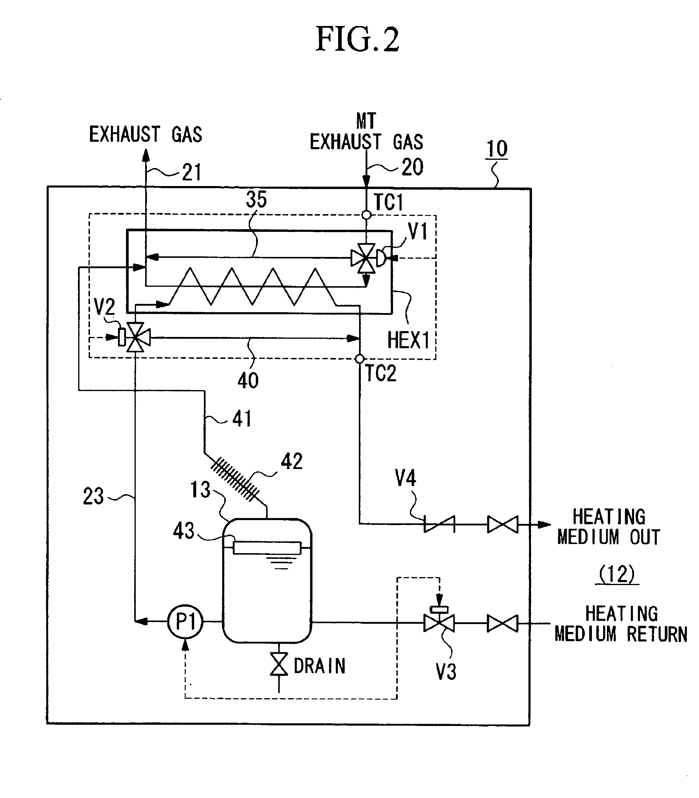
[0042]FIG. 2 is a drawing showing the exhaust heat recovery system 10, and the exhaust heat recovery system 10 of the present embodiment heats a heating medium circulated and used in a predetermined facility such as an air conditioner by using the heat of the exhaust gas generated by the electric power generator.
[0043]In FIG. 2, HEX1 is a heat exchanger for exhaust heat recovery that heats a heating medium by carrying out heat exchange between exhaust gas and the heating medium. Reference numeral 13 is a heat storage tank acting as a buffer tank that temporarily stores the heating medium that has been heated by the heat exchanger HEX1 for exhaust heat recovery, and P1 is a pump for conveying the heating medium. Moreover, water (hot water) or chemicals can be used as a heating medium.
[0044]The gas turbine MT (refer to FIG. 1) and the heat exchanger HEX1 for exhaust heat recovery are connected by the exhaust gas feed pipe 20. A temperature sensor TC1 that detects the temperature of th...
third embodiment
[0083]Next, the exhaust heat recovery system of the present invention will be explained.
[0084]FIG. 7 is a drawing showing the structure of the embodiment of the exhaust heat recovery system 10. The exhaust heat recovery system 10 of the present embodiment uses the heat of the exhaust gas generated by an electric generator, and heats water for hot water supply.
[0085]Moreover, essential components having a function identical to those already explained in each of the embodiments described above are denoted by the same reference numbers.
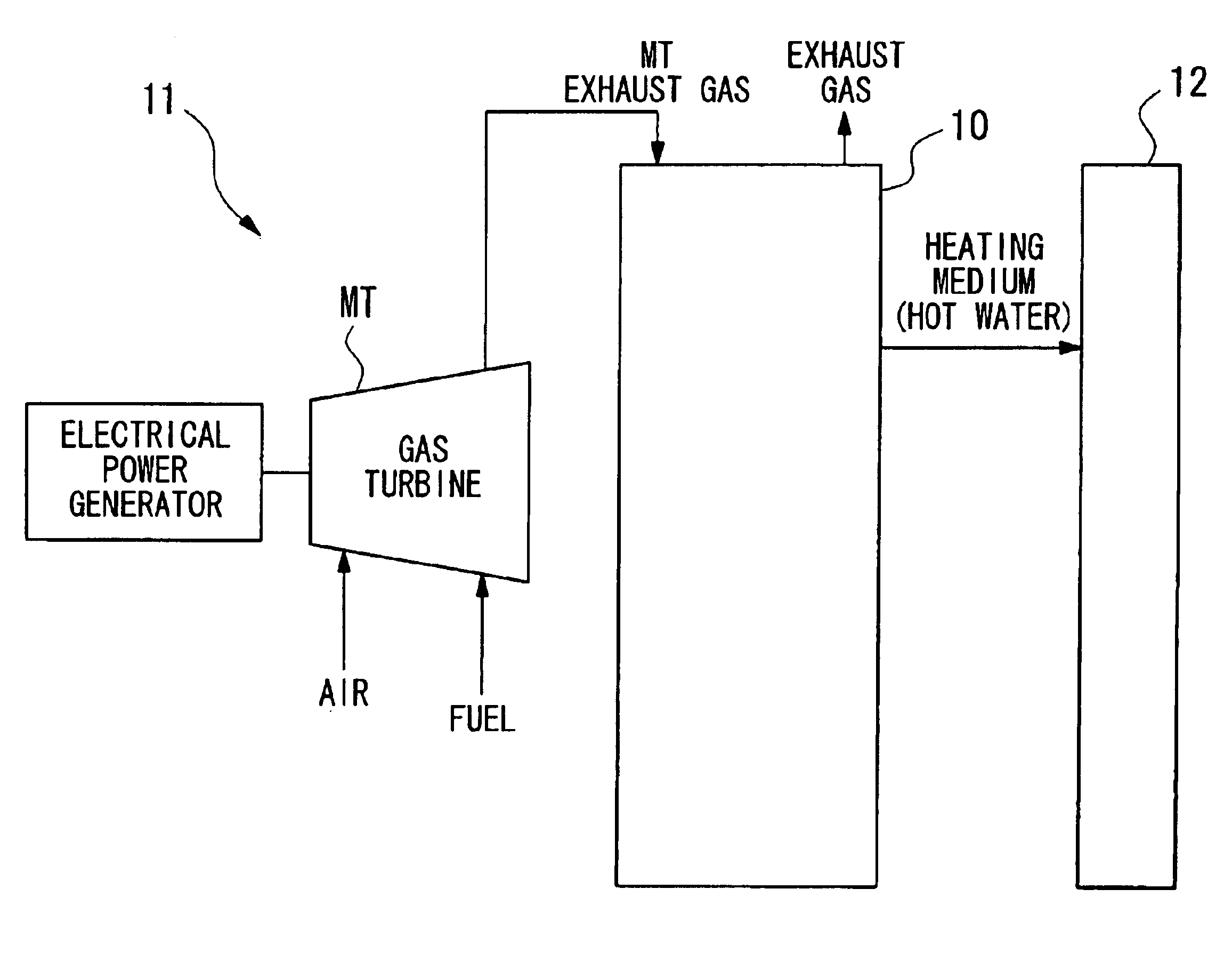
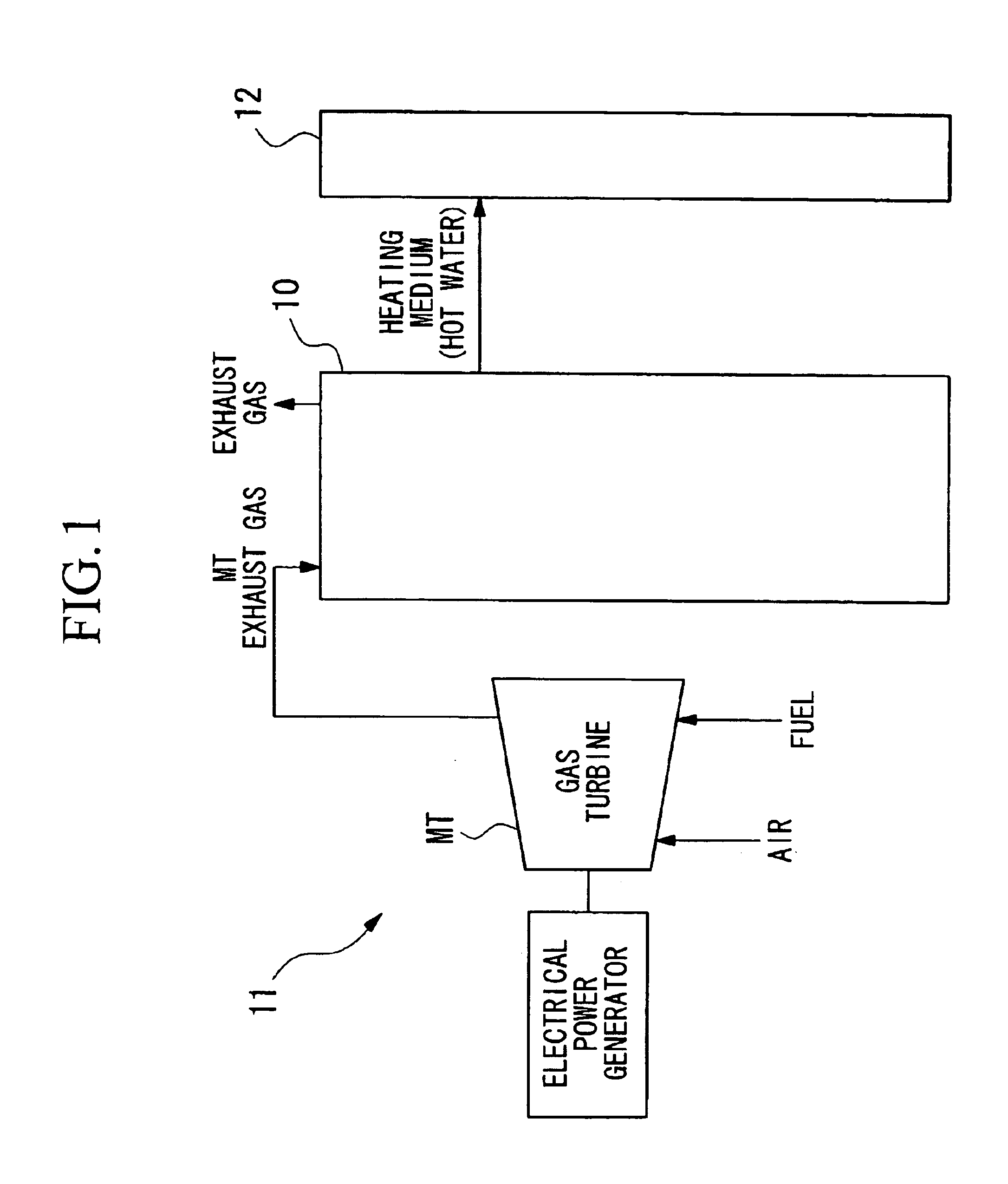
[0086]In addition, as shown in FIG. 1 above, the self-supply type electrical power supply system 11 having attached the exhaust heat recovery system 10 themselves obtain electricity by driving an electrical generator using a small-scale gas turbine MT (micro gas turbine) as a drive source. The exhaust heat recovery system 10 recovers the heat of the exhaust gas generated by the gas turbine when the electrical generator is being driven.
[0087]In FIG. 7, HE...
fourth embodiment
[0113]Next, the exhaust heat recovery system of the present invention will be explained.
[0114]FIG. 10 is a drawing showing the structure of the embodiment of the exhaust heat recovery system 10. The exhaust heat recovery system 10 of the present embodiment, the water (hot water) used and circulated is heated by using the heat of the exhaust gas generated in an electric power generator. As a facility 12 (a facility that uses hot water) that circulates and uses the hot water, for example, a floor heating apparatus, an absorption type water heater / cooler and the like can be given as air conditioning apparatuses that use heat. Furthermore, by using an indirect heat exchanger as the predetermined facility 12, it can be used for various heating, including potable hot water.
[0115]Moreover, essential components having a function identical to those already explained in each of the embodiments described above are denoted by the same reference numbers.
[0116]In addition, as shown in the FIG. 1 ...
PUM
 Abstract
Description
Claims
Application Information
 - R&D
- Intellectual Property
- Life Sciences
- Materials
- Tech Scout
- Unparalleled Data Quality
- Higher Quality Content
- 60% Fewer Hallucinations
Browse by: Latest US Patents, China's latest patents, Technical Efficacy Thesaurus, Application Domain, Technology Topic, Popular Technical Reports.
© 2025 PatSnap. All rights reserved.Legal|Privacy policy|Modern Slavery Act Transparency Statement|Sitemap|About US| Contact US: help@patsnap.com