[0021]Accordingly, it is a principle
advantage of the present invention to overcome some or all of these limitations and to provide an improved downhole drilling tractor.
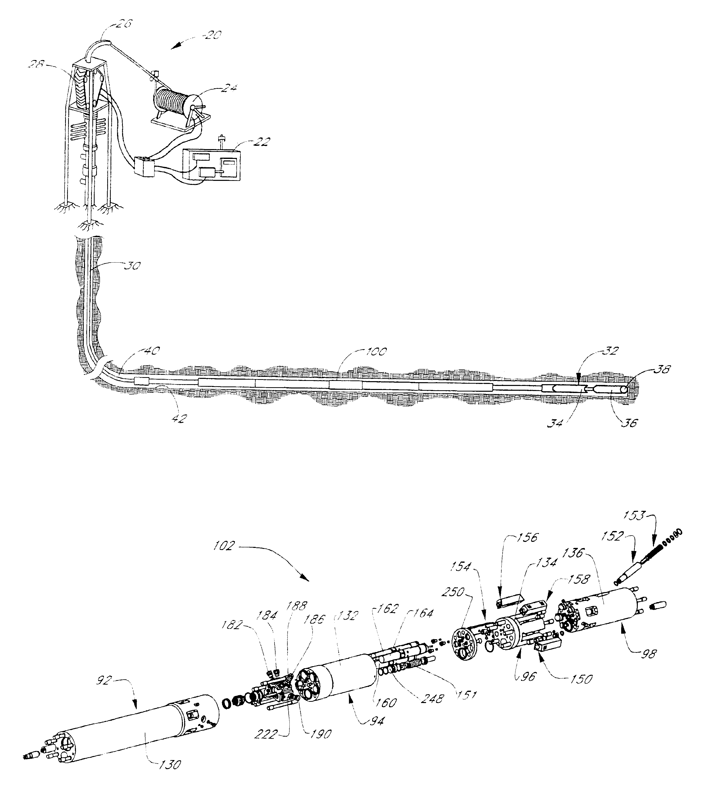
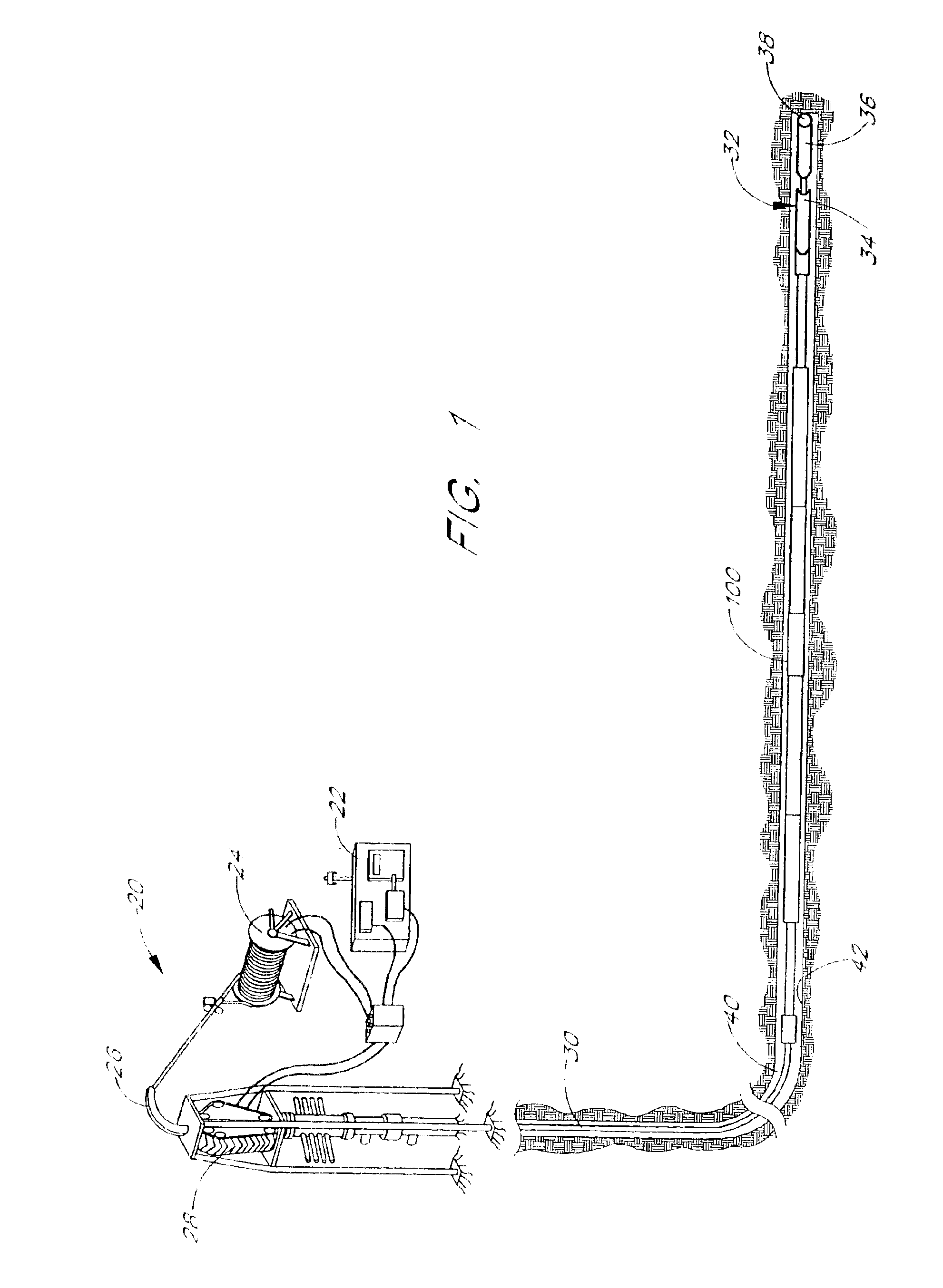
[0022]The structural configuration of the tractor, which allows it to work within the harsh environment and limited space within the bore of an
oil well, is an important aspect of the invention. An important aspect of the invention is the structural configuration that permits the tractor to fit within an envelope no more than 8.5 inches in
diameter and, preferably, no more than 2.875 inches in
diameter. This relatively small
diameter permits the tractor to work with standard
oil well equipment that is designed for 2.875-8.5 inch diameter well bores. Another important aspect of the present invention is the structural configuration that permits the tractor to make relatively sharp turns. Specifically, the tractor desirably has a length of no more than 150 feet, more desirably no more than 100 feet, more desirably no more than 75 feet, more desirably no more than 50 feet, and even more desirably no more than 40 feet. Preferably the length of the tractor is approximately 32 feet. Advantageously, the tractor can turn at least 60° per 100 feet of travel. Yet another important aspect of the invention is a structure that permits the tractor to operate at downhole pressures up to 16,000 psi and, preferably, 5,000-10,000 psi, and downhole temperatures up to 300° F. and, preferably, 200-250° F. Preferably, the tractor can operate at differential pressures of 200-2500 psi, and more preferably within a range of 500-1600 psi (the pressure differential between the inside and outside of the EST, thus across the internal flow channel and the annulus surrounding the tractor).
[0023]One limitation of prior art tractors that have valves whose positions control fluid flow providing thrust to the tractor body is that such valves tend to operate only at extreme positions. These valves can be characterized as having distinct positions in which the valve is either on or off, open or closed, etc. As a result, these valves fail to provide fine-tuned control over the position, speed, thrust, and direction of the tractor.
[0024]In another aspect, the present invention provides a tractor for moving within a borehole, which is capable of an exceptionally fast response to variations in load exerted on the tractor by the borehole or by external equipment such as a
bottom hole assembly or
drill string. The tractor comprises a tractor body sized and shaped to move within a borehole, a valve on the tractor body, a motor on the tractor body, and a coupler. The valve is positioned along a flowpath between a source of fluid and a thrust-receiving portion of the body. The valve comprises a fluid port and a flow restrictor. The flow restrictor has a first position in which the restrictor completely blocks fluid flow through the fluid port, a range of second positions in which the restrictor permits a first level of fluid flow through the fluid port, a third position in which the restrictor permits a second level of fluid flow through the fluid port. The second level of fluid flow is greater than the first level of fluid flow. The coupler connects the motor and the flow restrictor, such that movement of the motor causes the restrictor to move between the first position, the range of second positions, and the third position. The restrictor is movable by the motor such that the net thrust received by the thrust receiving portion can be altered by 100 pounds within 0.5 seconds.
[0025]One goal of the present invention is to provide a downhole tractor which provides an exceptional level of control over position, speed, thrust, and change of direction of the tractor within a borehole, compared to prior art tractors. Accordingly, in one aspect the present invention provides a tractor for moving within a hole, comprising a tractor body having a plurality of thrust receiving portions, at least one valve on the tractor body, and a plurality of
grippers. The valves are positioned along at least one of a plurality of fluid flow paths between a source of fluid and the thrust receiving portions. Each of the plurality of
grippers is longitudinally movably engaged with the body and has an actuated position in which the gripper limits movement of the gripper relative to an inner surface of the borehole and a retracted position in which the gripper permits substantially free relative movement of the gripper relative to the inner surface. The plurality of
grippers, the plurality of thrust receiving portions, and the valves are configured such the tractor can propel itself at a sustained rate of less than 50 feet per hour and at a sustained rate of greater than 100 feet per hour.
[0026]In other embodiments, the tractor can propel itself at sustained rates of less than 30 feet per hour and greater than 100 feet per hour, less than 10 feet per hour and greater than 100 feet per hour, less than 5 feet per hour and greater than 100 feet per hour, less than 50 feet per hour and greater than 250 feet per hour, and less than 50 feet per hour and greater than 500 feet per hour. In another embodiment, the source of fluid has a
differential pressure in the range of 200-2500 psi. In another embodiment, the source of fluid has a
differential pressure in the range of 500-1600 psi. In another embodiment, the tractor can change the rate at which it propels itself without a change in
differential pressure of the fluid. In various embodiments, the tractor has a length preferably less than 150 feet, more preferably less than 100 feet, even more preferably less than 75 feet, even more preferably less than 50 feet, and most preferably less than 40 feet. In various embodiments, the tractor has a
maximum diameter preferably less than eight inches, more preferably less than six inches, and even more preferably less than four inches.

