Container for welding wire

a technology for welding wire and containers, applied in containers, tray containers, containers for annular objects, etc., can solve the time-consuming and time-consuming problems of the described procedure from opening to re-mounting the lid, and achieve the effect of improving the sorting of wire layers and avoiding unwanted wire bending

Inactive Publication Date: 2005-09-06
SIDERGAS
View PDF21 Cites 47 Cited by
  • Summary
  • Abstract
  • Description
  • Claims
  • Application Information

AI Technical Summary

Benefits of technology

[0010]This arrangement avoids deformation of the coil and the body during transportation or stacking. When the wire is unwound from the coil and the height of the coil decreases, the above-mentioned retainer can easily descend, sliding unhindered along the stabilising elements. The present invention provides a container with cheap stabilising elements of superior stability which prevent the container from deformation and which allows a more continuous feed of the wire. Further, the corner supports still leave enough empty space in the corners of the polygonal body in which tips of a retainer braking element, made of plastic, wire or any other material, can extend beyond the wire coil to prevent wire strands from lifting along an outer perimeter of the wire coil.
[0041]In order to achieve the above object and to avoid the above disadvantages, the invention provides a container for welding wire comprising a box-like body having a bottom and a side wall and comprising a lid at the top of the body for closing the container. The central core arranged on the bottom tapers in the upward direction. According to the preferred embodiment, the core has a frusto-conical or pyramidal shape. By using a tapering core the wire comes out at a smoother angle, gently touching on the whole length of the core. Wearing at the upper edge of the core can be avoided.

Problems solved by technology

However, the described procedure from opening to re-mounting of the lid is time-consuming.
Further, it cannot be excluded that the container remains opened for some hours or days after removing the lid allowing dirt and moisture to enter into the container so that the wire is soiled or immediately oxidises.
A further reason that the container according to the state of the art is opened by the purchaser of the container is that the inspection windows do not allow a complete inspection of the interior for initiating the welding process or during the welding process, in order to check the quality of the wire and the remaining content of the container, respectively.

Method used


Image

  • Container for welding wire
  • Container for welding wire
  • Container for welding wire

Examples


Embodiment Construction

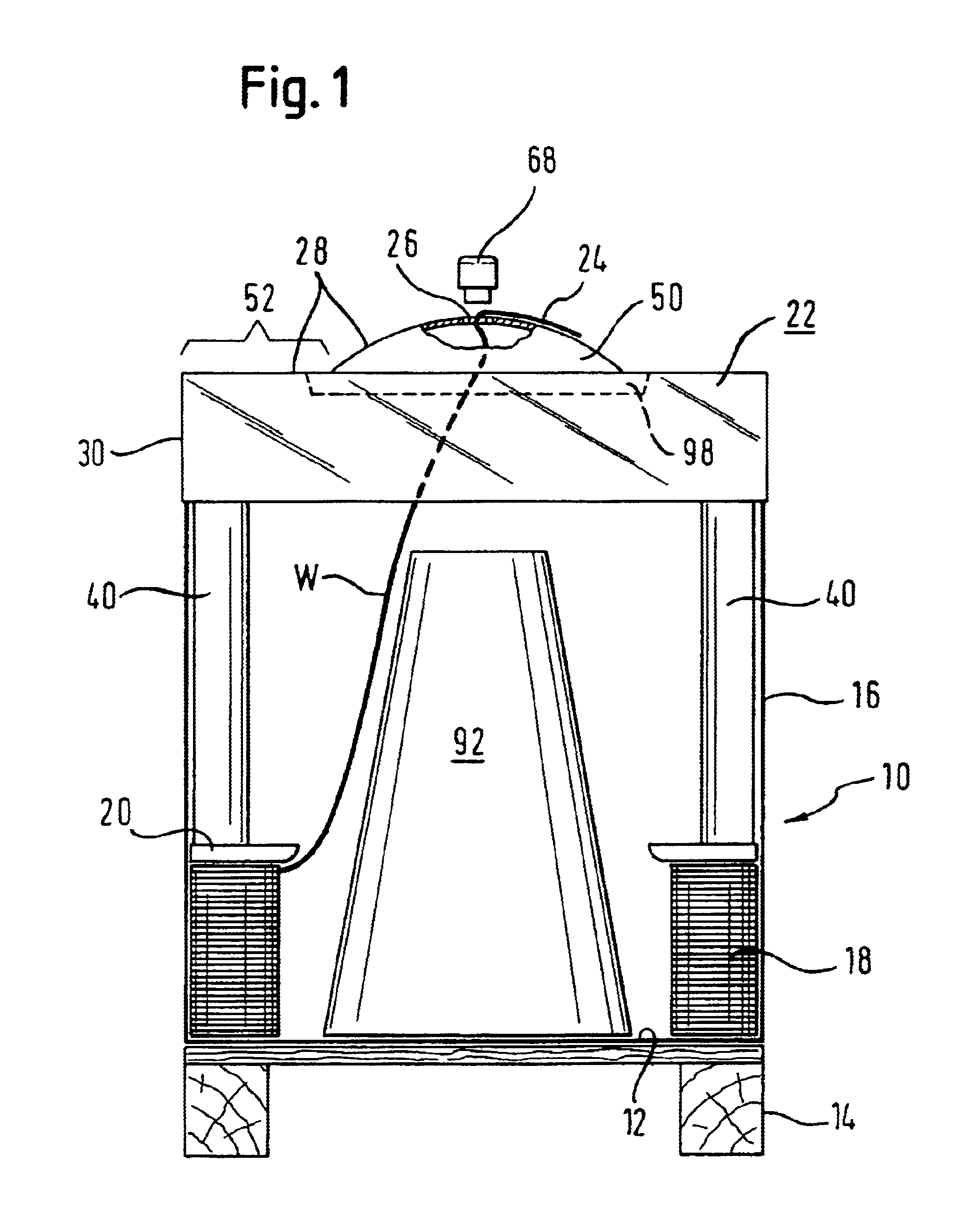
[0057]A container for accommodating of welding wire W according to a first embodiment is shown in FIG. 1. The container comprises as main components a box-like body 10 having a bottom 12 which is supported by a pallet 14 defining a lower part of the bottom. The box-like body further has a side wall 16 which is, in the circumferential direction, closed. The bottom and the side wall are, according to the preferred embodiment, made from cardboard. The pallet 14 is of wood.

[0058]A coil 18 of welding wire W is arranged within the container. A retainer 20, which is ring-shaped, sits on the welding wire W for downholding the wire coil strands. The upper end of the wire extends upwards from the retainer 20 to a lid 22 which closes the container and which is placed on top of the box-like body 16 which latter having an open upper side. The lid 22 has a central wire-exiting hole 24 through which the wire end 24 extends even in the shipping state which is shown in FIG. 1. The wire-exiting hole ...


PUM

PropertyMeasurementUnit
angleaaaaaaaaaa
thicknessaaaaaaaaaa
thicknessaaaaaaaaaa

Abstract

A container for welding wire comprises a box-like body having a bottom and a side wall, the side wall having a polygonal cross section with corners, and stabilizing elements arranged at at least some of the corners. The stabilizing elements extend upwardly from the bottom and have an outer shell portion comprising a corner portion facing the adjacent side wall and an inner portion facing an interior of the container for housing welding wire. The corner portion has a shape adapted to the shape of the adjacent corner. The inner portion defines a continuous inner wall.

Description

TECHNICAL FIELD[0001]The invention relates to a container for welding wire.BACKGROUND OF THE INVENTION[0002]A container for welding wire serves to accommodate a bulk welding wire coil used in automatic and semi-automatic welding processes. The container has two primary functions. First, the container serves as a means for transporting the welding wire coil and protecting it. In particular, the container is to be made sufficiently rigid to prevent the individual turns of the welding wire coil to be displaced one relatively to the other. Second, the container serves as take-out device allowing continuous withdrawal of the welding wire from the coil.[0003]When the container is completely filled with the wire, the wire exerts a radial pressure into the side wall which tends to deform the polygonal container.[0004]To avoid such deformation, EP 0 636 098 B1 suggests to place a stabilising device at each corner of the side wall which device extends upwardly from the bottom and comprises an...

Claims


Application Information

Patent Timeline
Patent Type & Authority Patents(United States)
IPC IPC(8): B65D81/05B65D5/50B65D85/02B65D71/00B65D85/04B65D19/44B65H49/00B65D19/38B65H49/08B23K9/133B65H57/18
CPCB23K9/1333B65D5/5045B65D5/5097B65D71/0096B65D81/05B65D85/04B65H49/08B65H57/18B65D2571/00055B65D2571/00074B65H2701/534
Inventor GELMETTI, CARLO
Owner SIDERGAS
Why Eureka
Try Eureka