Method and system for manufacturing DRAMs with reduced self-refresh current requirements

Inactive Publication Date: 2005-09-06
POLARIS INNOVATIONS
View PDF18 Cites 50 Cited by
  • Summary
  • Abstract
  • Description
  • Claims
  • Application Information

AI Technical Summary

Benefits of technology

[0012]The present invention relates to a method and system for reducing self-refresh current requirements in a DRAMs. A DRAM chip is sectioned into a number of segments. The entire DRAM chip is tested upon manufacture to determine the relative decay rates for each cell in the DRAM. For each respective segment, the refresh rate for that segment is selected in accordance with the fastest decay rate for a DRAM cell in that segment. The DRAM is configured

Problems solved by technology

The charge levels that are stored in the capacitors of the DRAM array are affected by leakage currents, which causes the stored voltage values to dissipate over time.
S

Method used


Image

  • Method and system for manufacturing DRAMs with reduced self-refresh current requirements
  • Method and system for manufacturing DRAMs with reduced self-refresh current requirements
  • Method and system for manufacturing DRAMs with reduced self-refresh current requirements

Examples


embodiment

Programmable Logic Embodiment

[0044]An advantage associated with the fuse-selectable embodiment is that the DRAM chip can be easily altered by laser-blowing fuses according to the outcome of chip testing for irregularities in charge decay times. As alternative, other types of programmable logic can be employed. Depending upon the particular implementation, other types of programmable logic may provide additional flexibility for determining whether memory cells in a segment are to be refreshed on each passage, alternate passages, every third passage, etc.

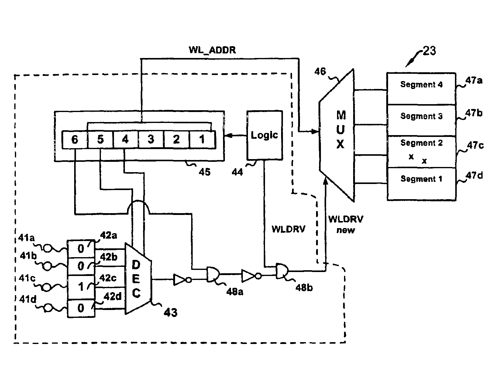
[0045]FIG. 6 illustrates the use of programmable logic for controlling the refresh of memory cells in a plurality of segments, according to a generic embodiment of the present invention. In this example, as in FIG. 4, the memory array is once again divided into four equal segments, each containing 8 word lines. Instead of using a 6 bit counter, a 5 bit counter (54321) is used, in which the two most significant bits determine which seg...


PUM


Abstract

A method and system for reducing self-refresh current requirements in a includes a DRAM chip that is sectioned into a number of segments. The entire DRAM chip is tested upon manufacture to determine the relative decay rates for each cell in the DRAM. For each segment, the refresh rate for that segment is selected based on the fastest decay rate for a DRAM cell in the segment. The DRAM is configured for refreshing memory cells during a self-refresh at different refresh rates for different segments. The refresh period is controlled for individual segments using techniques, such as programmable logic or fuses, to skip certain self-refresh cycles for those segments capable of operating at lower refresh rates. The refresh period in memory segments with strong memory cells can be reduced, thereby conserving current required to be drawn.

Description

BACKGROUND OF THE INVENTION[0001]1. Field of the Invention[0002]The present invention relates to self-refresh circuits in semiconductor memory devices, and more particularly, to a system and method for reducing self-refresh current requirements.[0003]2. Background Information[0004]In the portable consumer electronics industry, recent advancements in microprocessor speeds and memory storage capabilities have resulted in a new generation of portable devices with significantly improved functionality. Along with additional features, portable electronic devices are continually being designed to operate more efficiently to draw less electrical current, and hence require less battery power. Such electronic devices (such as laptops, digital cameras, digital cellular telephones, personal digital assistants) are now capable of operating for longer periods of time before requiring battery replacement or recharge, which can be useful to consumers and are less expensive to operate.[0005]Many por...

Claims


Application Information

Patent Timeline
IPC IPC(8): G11C11/406
CPCG11C11/406G11C11/40615G11C2211/4061
Inventor POECHMUELLER, PETER
Owner POLARIS INNOVATIONS
Why Eureka
Try Eureka